Rippled mixers for uniformity and color mixing

Active Publication Date: 2007-02-01
SYNOPSYS INC
View PDF38 Cites 147 Cited by
  • Summary
  • Abstract
  • Description
  • Claims
  • Application Information

AI Technical Summary

Benefits of technology

[0022] In certain embodiments, a lighting apparatus comprises a light source comprising a plurality of emitters and a mixer having an input and an output and a central region therebetween. The mixer comprises at least one rippled surface in the central region comprising a plurality of peaks and valleys connected by sloping surface po

Problems solved by technology

However, known mixing rods suffer from various drawbacks inc

Method used


Image

  • Rippled mixers for uniformity and color mixing
  • Rippled mixers for uniformity and color mixing
  • Rippled mixers for uniformity and color mixing

Examples


Embodiment Construction

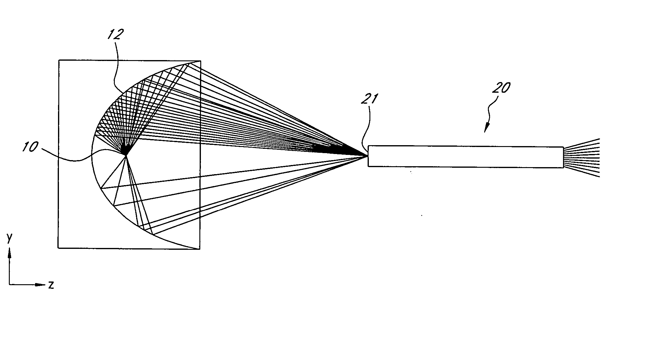
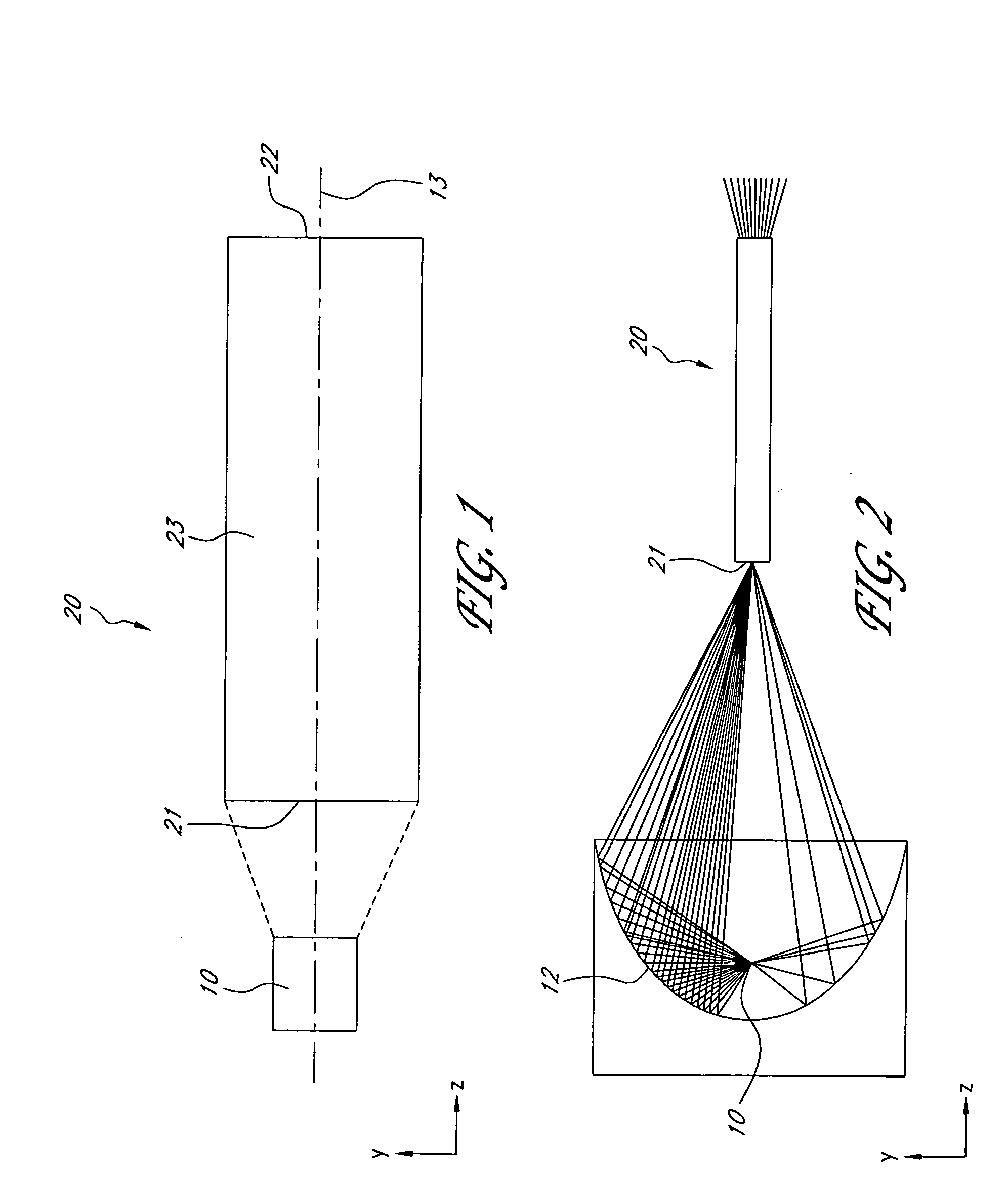
[0149] Many illumination designs benefit from homogenized light. Accordingly, efforts have been made to obtain substantially uniform illuminance distributions from light sources, such as light emitting diodes (LEDs), that produce non-uniform illuminance distributions. One known method of achieving this goal employs mixing rods. In many embodiments, flux from a light source is transferred to an input end of a mixing rod. The flux propagates through the mixing rod, typically reflecting from the sidewalls of the mixing rod one or more times. In certain embodiments, coupling a light source that produces a non-uniform illuminance distribution with the input end of the mixing rod produces a substantially uniform illuminance distribution at an output end of the mixing rod.

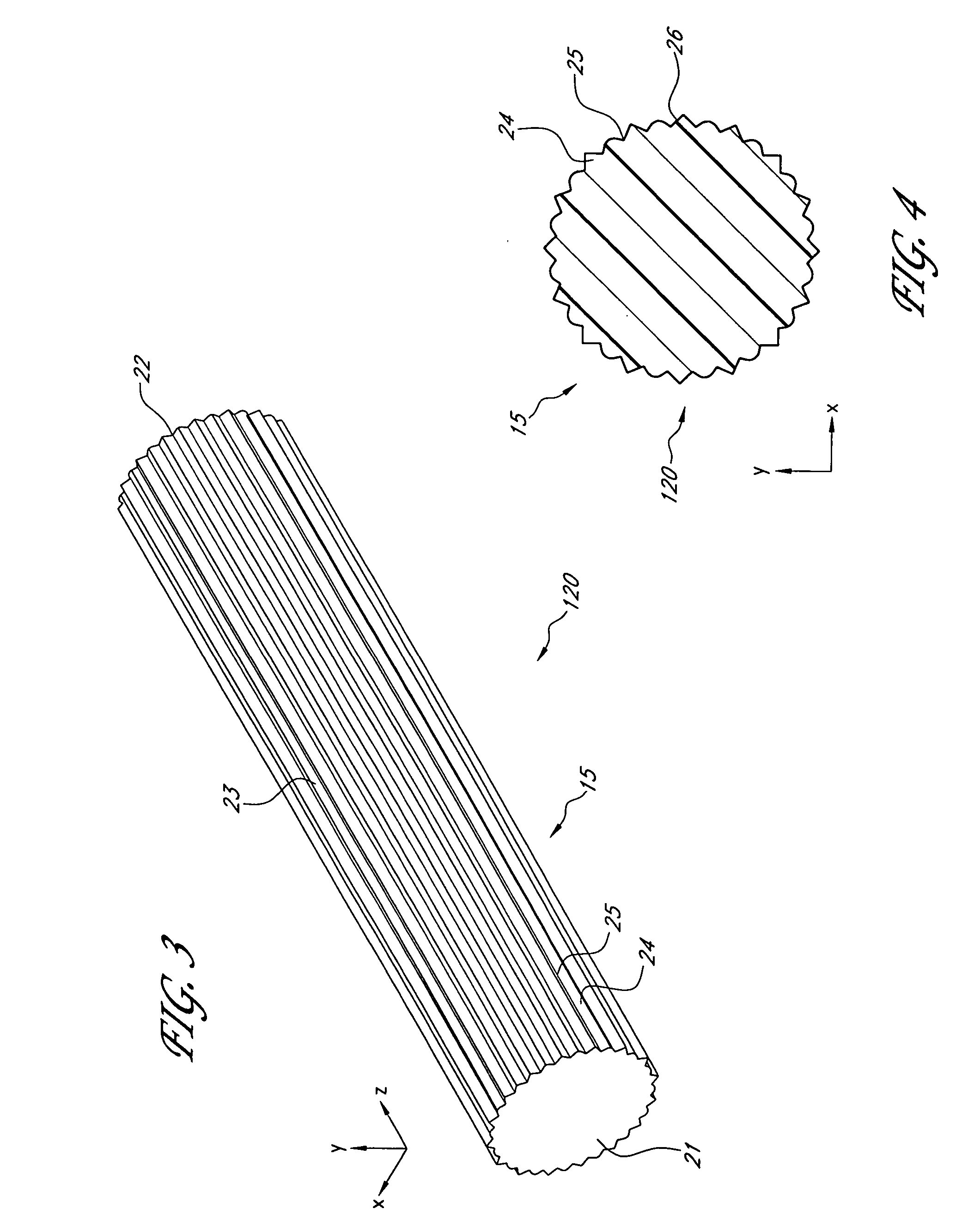
[0150] Certain mixing rod configurations are particularly effective in achieving substantially uniform illuminance distributions. For example, straight rods having rectangular or hexagonal cross-sections are known to wor...


PUM


Abstract

Various embodiments described herein comprise mixers comprising a light pipe having input and output ends and a central region therebetween. An optical path extends in a longitudinal direction from the input end through the central region to the output end. The central region of the light pipe comprises one or more rippled reflective sidewalls having a plurality of elongate ridges and valleys and sloping surfaces therebetween. Light from the input end propagating along the optical path reflects from the sloping surfaces and is redirected at a different azimuthal direction toward the output end thereby mixing the light at the output end. Illuminance and/or color mixing can therefore be provided.

Description

CROSS-REFERENCE TO RELATED APPLICATIONS [0001] This application claims the benefit under 35 U.S.C. § 119(e) of U.S. Provisional Application No. 60 / 703,808, filed Jul. 29, 2005, titled RIPPLED MIXERS FOR UNIFORMITY AND COLOR MIXING, the entire contents of which are hereby incorporated by reference herein and made a part of this specification.BACKGROUND [0002] 1. Field of the Inventions [0003] Certain embodiments disclosed herein relate generally to structures for mixing light, such as for example mixing rods, and relate more specifically to light-mixing structures having multiple ridges and valleys. [0004] 2. Description of the Related Art [0005] It is a common practice to improve the uniformity of light by coupling light sources with mixing rods. This practice can homogenize illuminance and color across a spatial region, as well as homogenize the intensity. However, known mixing rods suffer from various drawbacks including limitations in the level of homogenization achievable. SUMMA...

Claims


Application Information

Patent Timeline
IPC IPC(8): G02B27/28
CPCG02B6/0008G02B6/0018G02B6/0038G02B27/0994G02B6/0096G02B6/4298G02B6/0068
Inventor CASSARLY, WILLIAM J.DAVENPORT, THOMAS L. R.MCGUIRE, JAMES P. JR.
Owner SYNOPSYS INC
Why Eureka
Try Eureka