Armored voice coil assembly for use in high power loudspeaker applications

a voice coil and high-power technology, applied in the direction of transducer details, electrical transducers, electrical apparatus, etc., can solve the problems of loudspeaker or woofer failure, excessive heat generation, and extreme excursions of the woofer's diaphragm, so as to achieve the effect of higher operating temperatures

Active Publication Date: 2007-02-01
ACOUSTIC DESIGN
View PDF15 Cites 16 Cited by
  • Summary
  • Abstract
  • Description
  • Claims
  • Application Information

AI Technical Summary

Benefits of technology

[0019] In use, armored voice coil assemblies can withstand higher operating temperatures and can also withstand, for a time, misalignment and resultant rubbing against the motor gap edge, since the coil's conductors are protected from damage by the stiffener or armor layer.

Problems solved by technology

In particular, high power signals drive a speaker's diaphragm or cone into extreme excursions and can cause the usually pistonic motion of the diaphragm to become mis-aligned when driven by more challenging audio signals.
Loudspeaker or woofer failure can be often attributed to thermal or mechanical overloading problems.
Substantial amounts of power are required to provide competition-winning sound pressure levels, and signals having such power require very large current flow through voice coil conductors, thus generating substantial amounts of heat and driving the woofer's diaphragm to extreme excursions.
Those extreme excursions generate extreme mechanical loads on the diaphragm and its supportive suspension.
In competitions, operators seek the loudest possible playback and often over-drive the loudspeaker drivers, causing voice coils to burn out or open circuit.
Such extreme use may also cause mechanical failure of the cone, the surround, the “spider” suspension member, or, when a moving, mis-aligned voice coil rubs the motor's annular gap edge, failure of the voice coil.
When assembling loudspeakers, one critical alignment step usually adds substantially to the cost and duration of the assembly operation.
If the assembler mis-aligns the voice coil in the annular magnetic gap, the voice coil may contact or rub the magnetic gap's edge, thereby causing distortion or failure of the loudspeaker.
The criticality of this alignment increases the cost of assembling loudspeakers.

Method used


Image

  • Armored voice coil assembly for use in high power loudspeaker applications
  • Armored voice coil assembly for use in high power loudspeaker applications
  • Armored voice coil assembly for use in high power loudspeaker applications

Examples


Embodiment Construction

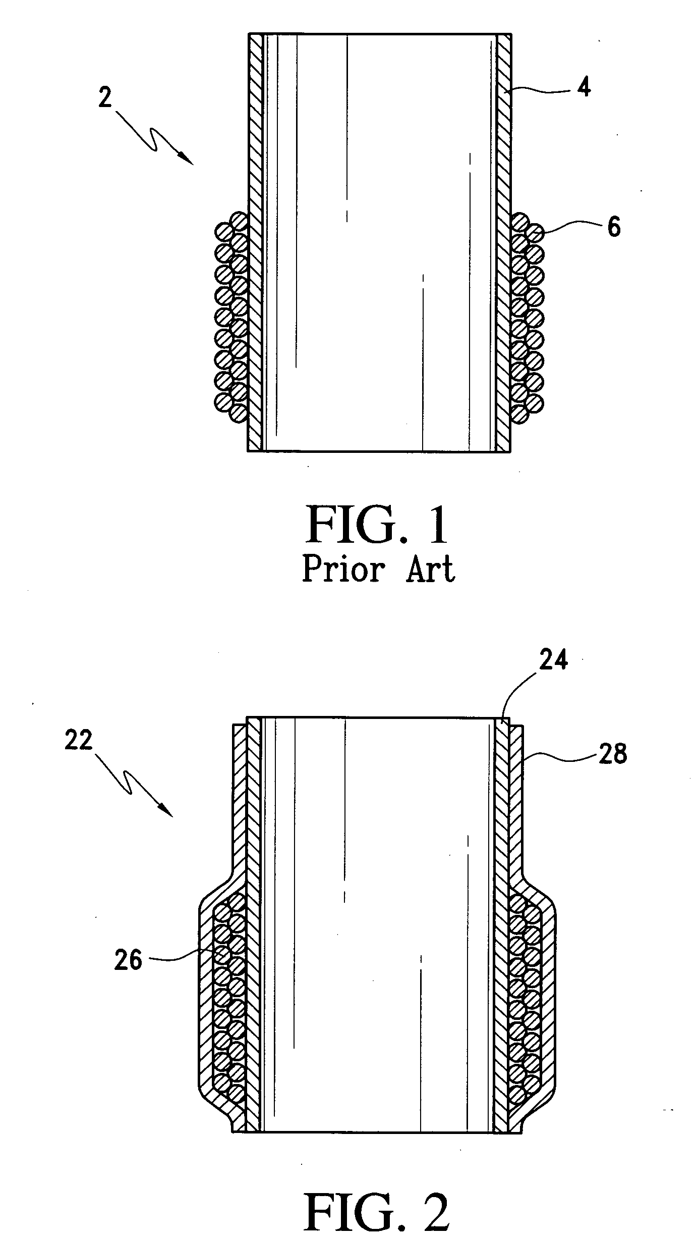
[0029] As illustrated in FIG. 1, a conventional voice coil 2 for use in a loudspeaker driver includes a cylindrical former 4 upon which is wrapped a plurality of turns of conductive wire to form a coil 6. The former 4 carries the coil 6 in a selected orientation for suspension in a driver motor's magnetic gap.

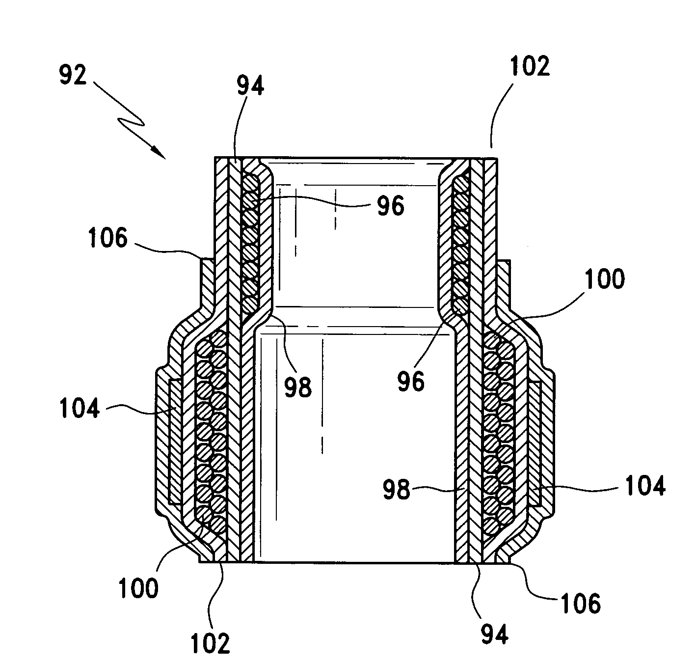
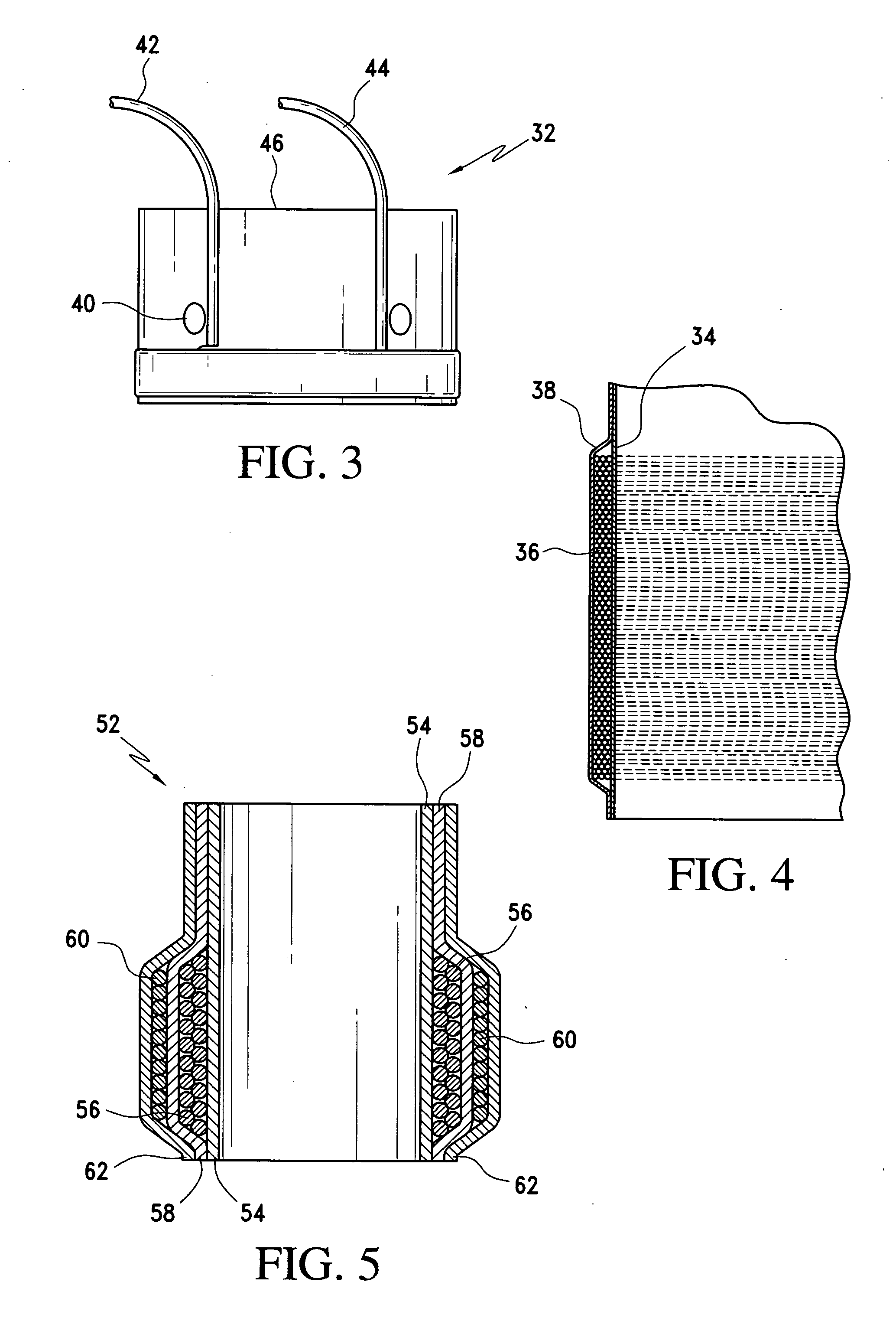
[0030]FIGS. 2-7 illustrate a few exemplary embodiments of the armored voice coil assembly of the present invention. Beginning with the embodiment of FIG. 2, an armored voice coil assembly 22 includes a former 24. The former 24 is tubular having a continuous wall with an exterior and interior surface forming a hollow interior. FIGS. 2-7 show a preferred cylindrical shape for the former 24. However, it is understood by one of ordinary skill in the art that the former 24 can be in any cross sectional shape. The former 24 is preferably made from a porous absorbent substrate impregnated with a curable resin. A variety of material may be selected as the porous absorbent substrate in...


PUM


Abstract

An armored voice coil assembly comprises a former that is impregnated with a curable resin, preferably polyimide resin. Voice coil wire is wound around the outside surface of the former and is then preferably encased with an outer layer of resin impregnated glass fabric wrapped around the voice coil windings, effectively enveloping the voice coil within inner and outer layers of fabric and resin. The armored voice coil assembly is then cured into a solid shape.

Description

CROSS-REFERENCE TO RELATED APPLICATIONS [0001] The present application claims priority to and the benefit, under 35 U.S.C. 119(e), of U.S. Provisional Application No., 60 / 703,009 filed on Jul. 28, 2005, the entire contents of which are incorporated herein by reference.BACKGROUND OF THE INVENTION [0002] 1. Field of the Invention [0003] The present invention relates to electromechanical loudspeaker motor structures, and, more particularly, to an armored voice coil assembly and methods for making armored voice coil assemblies for use in high power, long excursion loudspeaker applications. [0004] 2. Description of Related Art [0005] Recent market emphasis on long excursion, high power dissipation loudspeakers (e.g., low frequency drivers or woofers) has challenged manufacturers to make products which will withstand previously unimaginable levels of abuse. DB drag races and other forms of loudness-level competition have created markets for amplifiers and loudspeakers dissipating several ...

Claims


Application Information

Patent Timeline
Patent Type & Authority Applications(United States)
IPC IPC(8): H04R9/06
CPCH04R9/022H04R9/046H04R9/045
Inventor YOUNG, LARRY J.
Owner ACOUSTIC DESIGN
Why Eureka
Try Eureka