Wafer heating apparatus and method of setting the apparatus

a heating apparatus and heating plate technology, applied in the field of wafer heating apparatus, can solve the problems of heterogeneous distribution, preventing control of uniformity, and affecting the uniformity of the heating plate,

Inactive Publication Date: 2007-02-01
SAMSUNG ELECTRONICS CO LTD
View PDF5 Cites 3 Cited by
  • Summary
  • Abstract
  • Description
  • Claims
  • Application Information

AI Technical Summary

Benefits of technology

[0014] The present invention provides a wafer heating apparatus that can form uniform interval distribution between a heating plate and a wafer by rectifying warpage of the heating plate.
[0015] The present invention also provides a wafer heating apparatus that can easily rectify warpage by controlling the flatness of the entire heating plate.
[0016] The present invention also provides a wafer heating apparatus of various structures which can control the flatness of a heating plate.
[0019] The wafer heating apparatus includes the pressing arm for partially pressurizing a peak of a warped heating plate or a portion adjacent to the peak and the arm controlling unit for controlling the level or pressure of the pressing arm. One or more pressing arms are located on the boundary between the side casing and the heating plate and disposed across the side casing and the heating plate. Each of the pressing arms may be in contact with the top of the heating plate by different pressure and may pressurize the peak of the heating plate, thereby maintaining approximately uniform flatness of the heating plate.

Problems solved by technology

In this case, the distortion of the heating plate, described above, may occur due to the heating pattern.
A distorted heating plate may cause heterogeneous distribution of the interval between the heating plate and wafer, and the heterogeneous interval distribution may prevent controlling the uniformity of the temperature of the wafer.

Method used


Image

  • Wafer heating apparatus and method of setting the apparatus
  • Wafer heating apparatus and method of setting the apparatus
  • Wafer heating apparatus and method of setting the apparatus

Examples


Embodiment Construction

[0033] Reference will now be made in detail to the embodiments of the present invention, examples of which are illustrated in the accompanying drawings, wherein like reference numerals refer to the like elements throughout. The embodiments are described below to explain the present invention by referring to the figures.

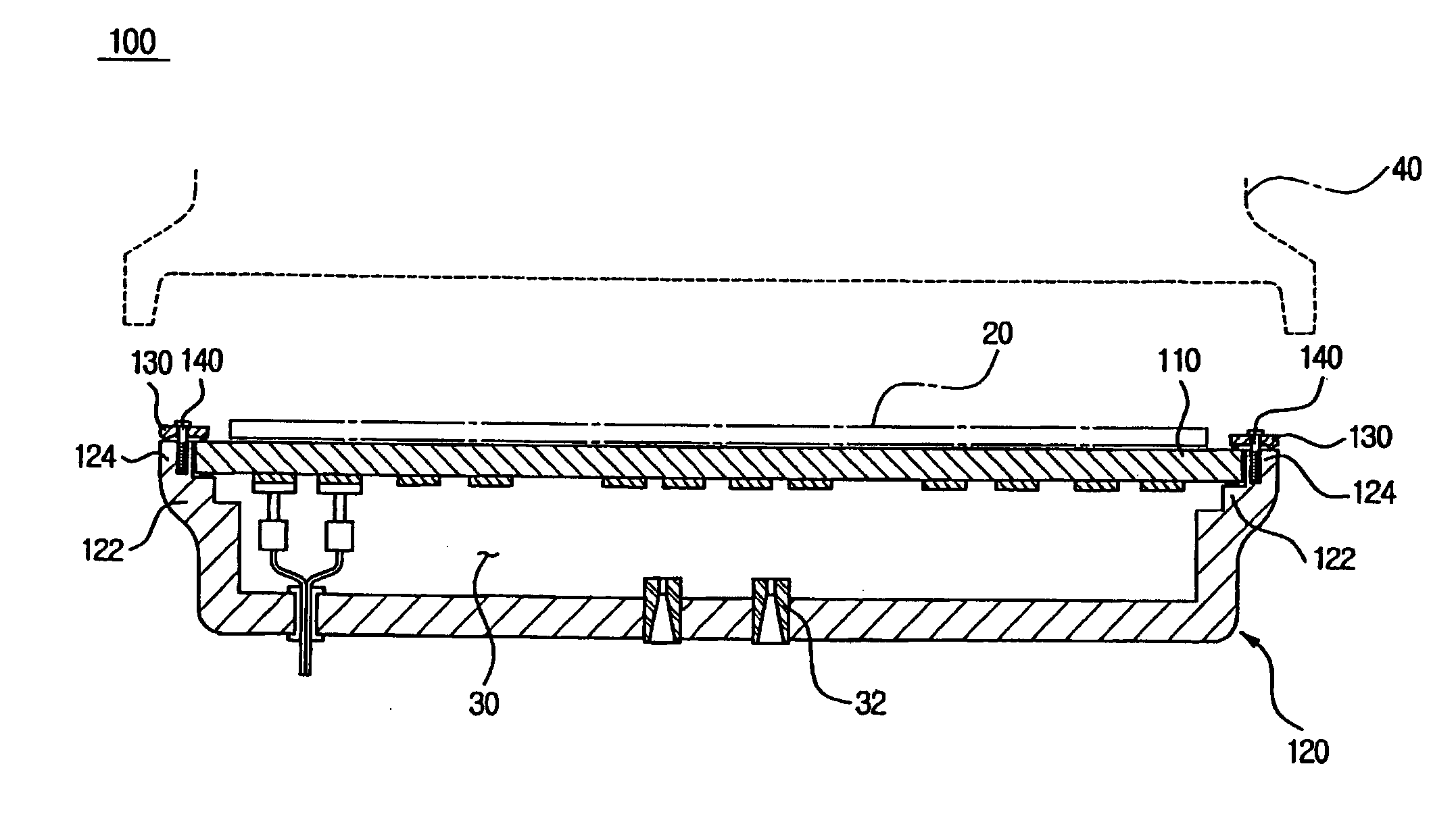
[0034]FIG. 3 is a cross-sectional view of a wafer heating apparatus according to an embodiment of the present invention, and FIG. 4 is a partial enlarged view illustrating a coupling relation between a heating plate and a pressing arm of FIG. 3.

[0035] Referring to FIGS. 3 and 4, a wafer heating apparatus 100 includes a heating plate 110, a case 120, pressing arms 130, and adjusting bolts 140. The case 120 supports the heating plate 110 and includes a space in the shape of a disk for containing the heating plate 110. The heating plate 110 may be securely disposed in the space, and the pressing arm 130 and the adjusting bolt 140 may fasten the heating plate 110 onto t...


PUM


Abstract

A wafer apparatus including a heating plate, a case supporting and containing the heating plate, pressing arms laid across the case and the heating plate, and arm controlling units vertically moving the pressing arm toward the case. A plurality of the pressing arms and the arm controlling units are disposed along the circumference of the heating plate and may compensate a portion protruded upward due to the warpage of the heating plate by pressurizing. The warpage of the heating plate can be effectively compensated, and a wafer can be heated with a uniform temperature.

Description

CROSS-REFERENCE TO RELATED APPLICATIONS [0001] This application claims the benefit of Korean Patent Application No. 2005-70211, filed on Aug. 1, 2005, in the Korean Intellectual Property Office, the disclosure of which is incorporated herein in its entity by reference. BACKGROUND OF THE INVENTION [0002] 1. Field of the Invention [0003] The present invention relates to a wafer heating apparatus, and more particularly, to a wafer heating apparatus and a method of setting the same, in which warpage of a plate, generated due to thermal deformation or the change of pressure is rectified. [0004] 2. Description of the Related Art [0005] Generally, a process of heating a wafer is frequently performed in manufacturing semiconductor devices. For example, a photolithography process includes sensitizing, exposing, developing, and etching. In this case, pre-baking and post exposure baking (PEB) may be respectively performed before and after the exposing. The described heating processes increase ...

Claims


Application Information

Patent Timeline
Patent Type & Authority Applications(United States)
IPC IPC(8): F26B19/00F26B3/30
CPCH01L21/67103H01L21/326
Inventor LEE, DONG WOOKIM, TAE GYULEE, JIN SUNG
Owner SAMSUNG ELECTRONICS CO LTD
Why Eureka
Try Eureka