Optical image stabilizer for camera lens assembly

Inactive Publication Date: 2007-02-01
SAMSUNG ELECTRONICS CO LTD +1
View PDF5 Cites 20 Cited by
  • Summary
  • Abstract
  • Description
  • Claims
  • Application Information

AI Technical Summary

Benefits of technology

[0014] Accordingly, the present invention has been made to solve the above-mentioned problems occurring in the prior art and provides additional advantages, by providing an optical image

Problems solved by technology

Due to mobility, images are distorted due to vibration or hand trembling arising from the human body.
Also, since it takes much time to correct distorted images, photographing speed may become slow.
Furthermore, since there is a limitation in removing afterimages using a software, the correction rate may deteriorate.
As an OIS needs a separate driving apparatus, manufacturing cost increases and an installation space must be provided.
However, due to limited available space in a small digital camera or a mobile communication terminal, this solution is not desirable.
However, in constructing an optical image stabilizer for a camera lens assembly, a flexible printed circuit connected to a camera device may lower the correction rate for hand trembling.
Therefore, the camera device needs a larger driving force due to the load of a flexible printed circuit.
Further, since the load of the flexible

Method used


Image

  • Optical image stabilizer for camera lens assembly
  • Optical image stabilizer for camera lens assembly
  • Optical image stabilizer for camera lens assembly

Examples


Example

[0027] An embodiment of the present invention will be described in detail herein below with reference to the accompanying drawings. For the purposes of clarity and simplicity, a detailed description of known functions and configurations incorporated herein will be omitted as it may obscure the subject matter of the present invention.

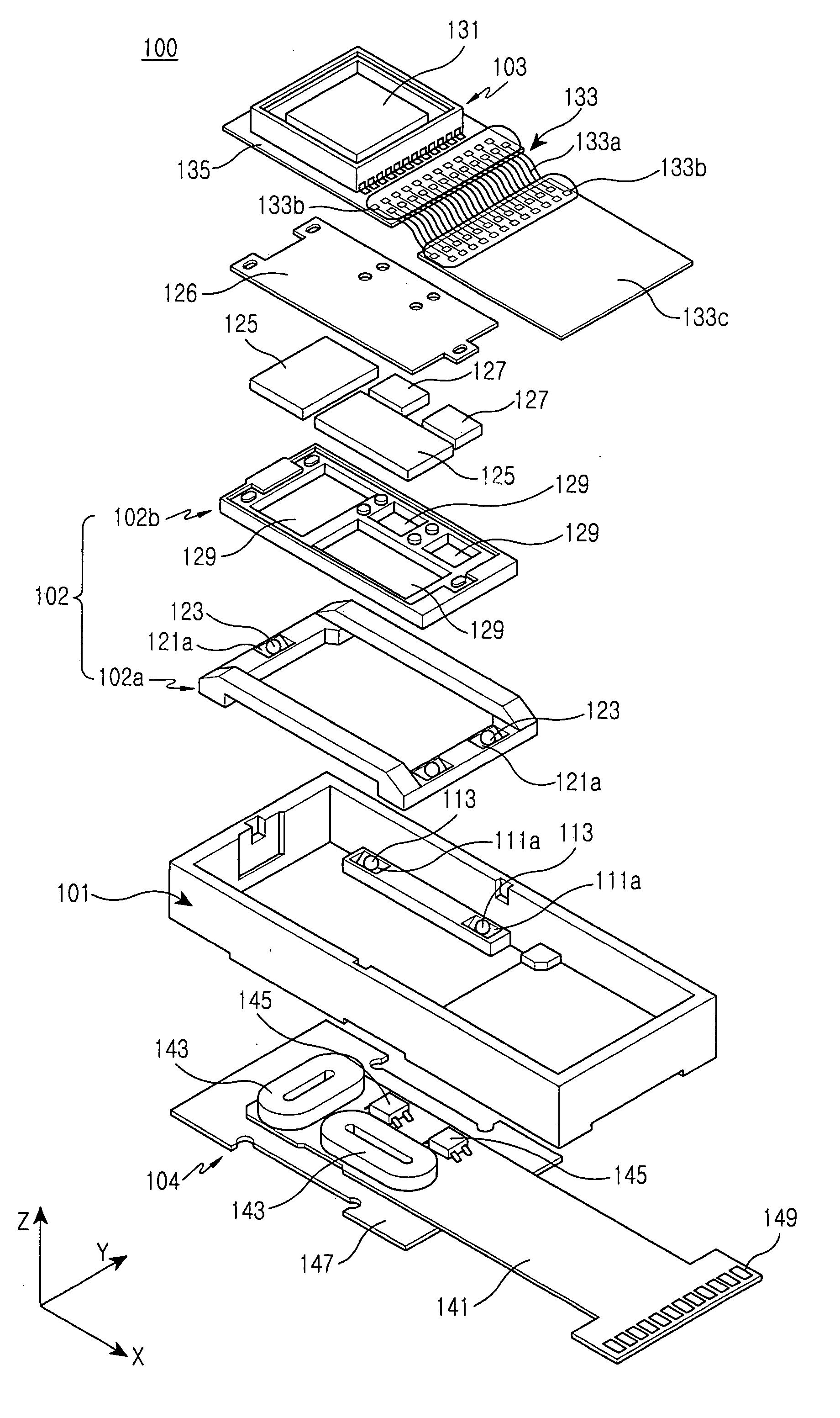
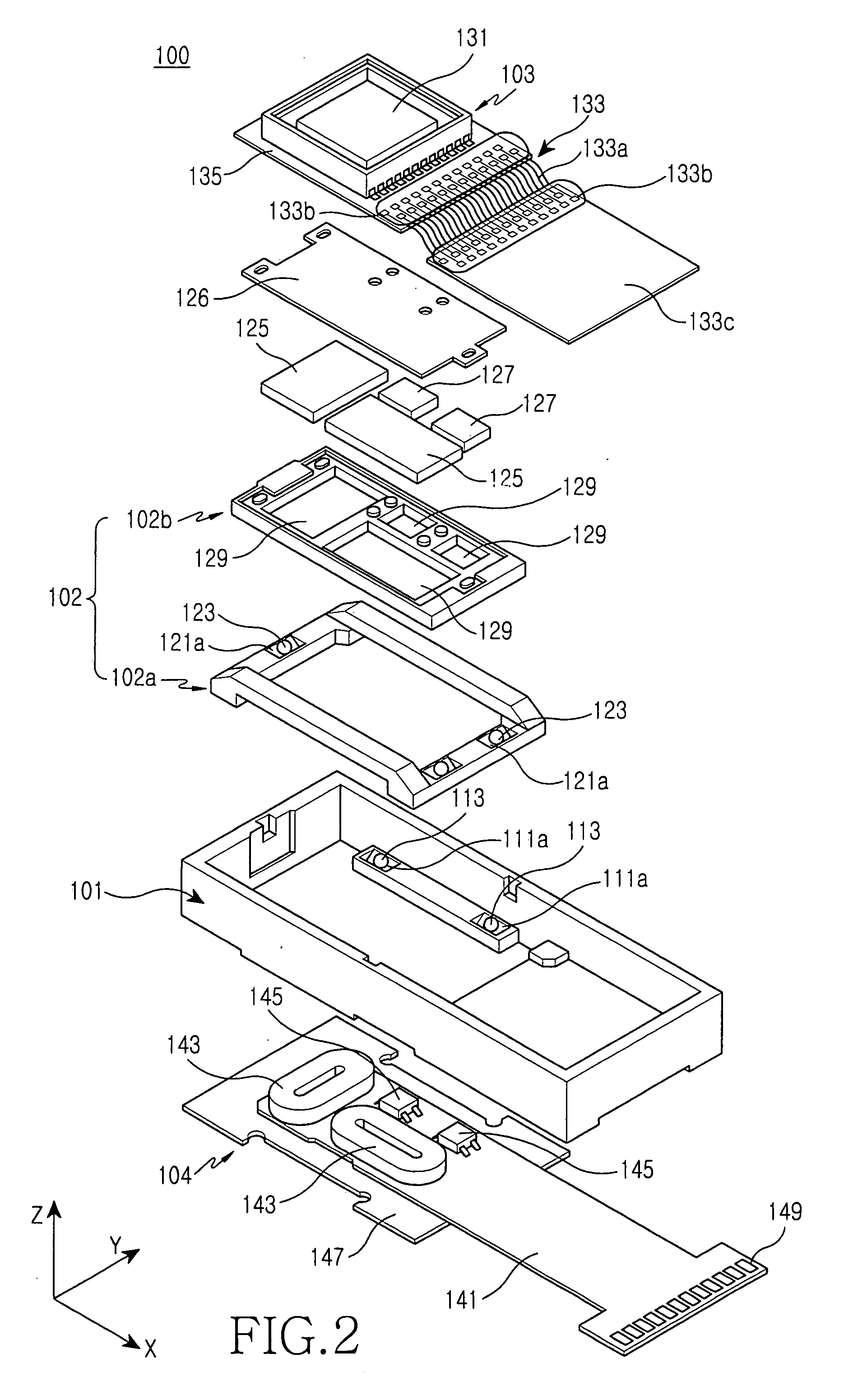
[0028] As illustrated in FIGS. 2 to 6, an optical image stabilizer 100 for a camera lens assembly according to an embodiment of the present invention includes a main frame 101, a driving frame 102, coils 143, and permanent magnets 125. The driving frame 102 moves on the main frame 101 by an interaction between the coils 143 and the permanent magnets 125, and changes the position of a camera device 103, so that it is possible to correct the distortion of photographed images which results from the hand trembling of a user.

[0029] Referring to FIGS. 2 and 4, the main frame 101 has an upper surface and a lower surface. The upper surface is at least partiall...


PUM


Abstract

An optical image stabilizer for use in a camera lens assembly includes: a main frame including a main circuit board; a driving frame installed so as to move on the main frame in at least one direction; a camera device including a sub-circuit board, the camera device being mounted on the driving frame; and a circuit connection for electrically connecting the main circuit board to the sub-circuit board, wherein the circuit connection includes both of its ends coupled to the main circuit board and the sub-circuit board, respectively, and a plurality of lead wires constructed so as to be moved separately with respect to the main circuit board and the sub-circuit board.

Description

CLAIM OF PRIORITY [0001] This application claims priority to an application entitled “Optical Image Stabilizer For Camera Lens Assembly,” filed in the Korean Intellectual Property Office on Jul. 28, 2005 and assigned Serial No. 2005-68967 and on Aug. 11, 2005 and assigned Serial No. 2005-73792, the contents of which are hereby incorporated by reference. BACKGROUND OF THE INVENTION [0002] 1. Field of the Invention [0003] The present invention relates to a camera lens assembly, and more particularly to an optical image stabilizer for correcting distorted images arising from hand trembling during photographing of an object. [0004] 2. Description of the Related Art [0005] With the recent development of a technology for miniaturizing and downsizing a digital camera, it has been possible to integrate a camera function to a mobile communication terminal. Therefore, the usage of a mobile communication terminal equipped with an optical lens and a camera device has been widely spread. [0006] ...

Claims


Application Information

Patent Timeline
IPC IPC(8): G03B17/00
CPCH04N5/2253H04N5/23248H04N5/23258H04N5/23287H05K2201/2009H05K3/3405H05K2201/10287H05K2201/10977H05K1/148H04N23/54H04N23/68H04N23/6812H04N23/687
Inventor SHIN, DOO-SIKSHIN, JEONG-KILKIM, HEE-SEUNGLEE, JONG-PILSEOL, JIN-SOO
Owner SAMSUNG ELECTRONICS CO LTD
Why Eureka
Try Eureka