Coloured liquid crystal display device

A liquid crystal display device, color technology, applied in transistors, static indicators, optics, etc., can solve problems such as increasing the complexity of the manufacturing process

Inactive Publication Date: 2004-10-20
TPO DISPLAY
View PDF0 Cites 3 Cited by
  • Summary
  • Abstract
  • Description
  • Claims
  • Application Information

AI Technical Summary

Problems solved by technology

If any thickness of the color filter layer 400 or the frame layer 300 needs to be changed due to the manufacturing process or product requi...

Method used


Image

  • Coloured liquid crystal display device
  • Coloured liquid crystal display device
  • Coloured liquid crystal display device

Examples


Embodiment Construction

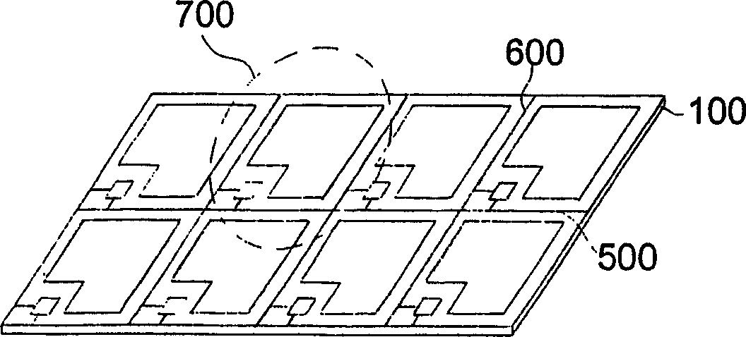
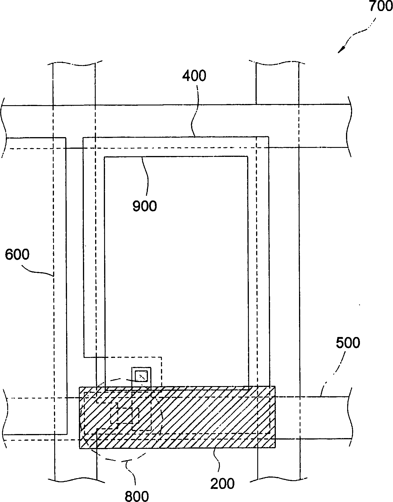
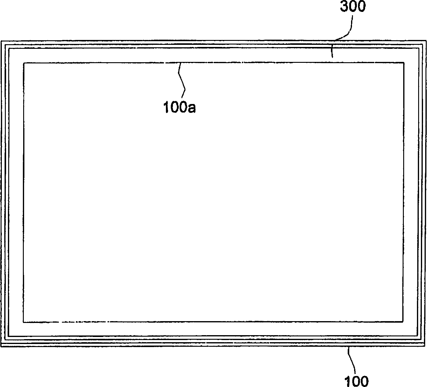
[0019] The invention provides a color liquid crystal display device, such as Figure 4 As shown, the device includes an array circuit substrate 100, a light-shielding layer 200 is formed on the array circuit substrate 100, and a frame layer 300 is included around the light-shielding layer 200 to prevent light leakage around the array circuit substrate 100. A color The filter layer 400 is formed on the array circuit substrate 100 and the light shielding layer 200 . The main feature of the liquid crystal display device is that the color filter layer 400 is extended to cover the frame layer 300 to reduce the difference between the liquid crystal region 1 and the liquid crystal region 2 . Covering the red, blue and green color filter layers on the frame layer can add a dielectric layer to reduce the circuit load, and the film thickness of the color filter layers can be adjusted flexibly. In this way, without affecting the gap between the upper and lower boards, the circuit load c...


PUM


Abstract

A color LCD is composed of an array circuit substrate with a scan line and a data line to form multiple pixels, a film transistor formed on a pixel, a pixel electrode for connecting said film transistor, a black matrix layer on said array circuit substrate, a frame layer surrounding said black matrix layer, and a color filter layer on said array circuit substrate and black matrix layer and extended to cover on frame layer.

Description

technical field [0001] The invention relates to a color liquid crystal display device and a method for manufacturing a color filter layer and a black matrix on an array substrate. Background technique [0002] A typical liquid crystal display device includes an upper substrate and a lower substrate, and a liquid crystal layer is sandwiched between the two substrates. The upper substrate has a color filter layer and a common electrode, and the lower substrate has a switch element and a pixel electrode. The lower substrate is called an array circuit substrate. The upper and lower bases are made separately and then connected together. During the formation of the upper substrate, there will be some heating processes, such as: pre-baking, exposure, post-exposure baking, etc., which may cause deformation of the upper substrate component, resulting in misalignment of the upper and lower substrates during connection. Therefore, if the color filter layer and the light-shielding lay...

Claims


Application Information

Patent Timeline
IPC IPC(8): G02F1/133G02F1/1335G02F1/136H01L29/786
Inventor 彭火花邱昌明郭光埌张景怡杨智胜
Owner TPO DISPLAY
Why Eureka
Try Eureka