
Apparatus and method for improving combustion stability

Inactive Publication Date: 2006-09-12
ANSALDO ENERGIA IP UK LTD
View PDF10 Cites 34 Cited by
  • Summary
  • Abstract
  • Description
  • Claims
  • Application Information

AI Technical Summary

Benefits of technology

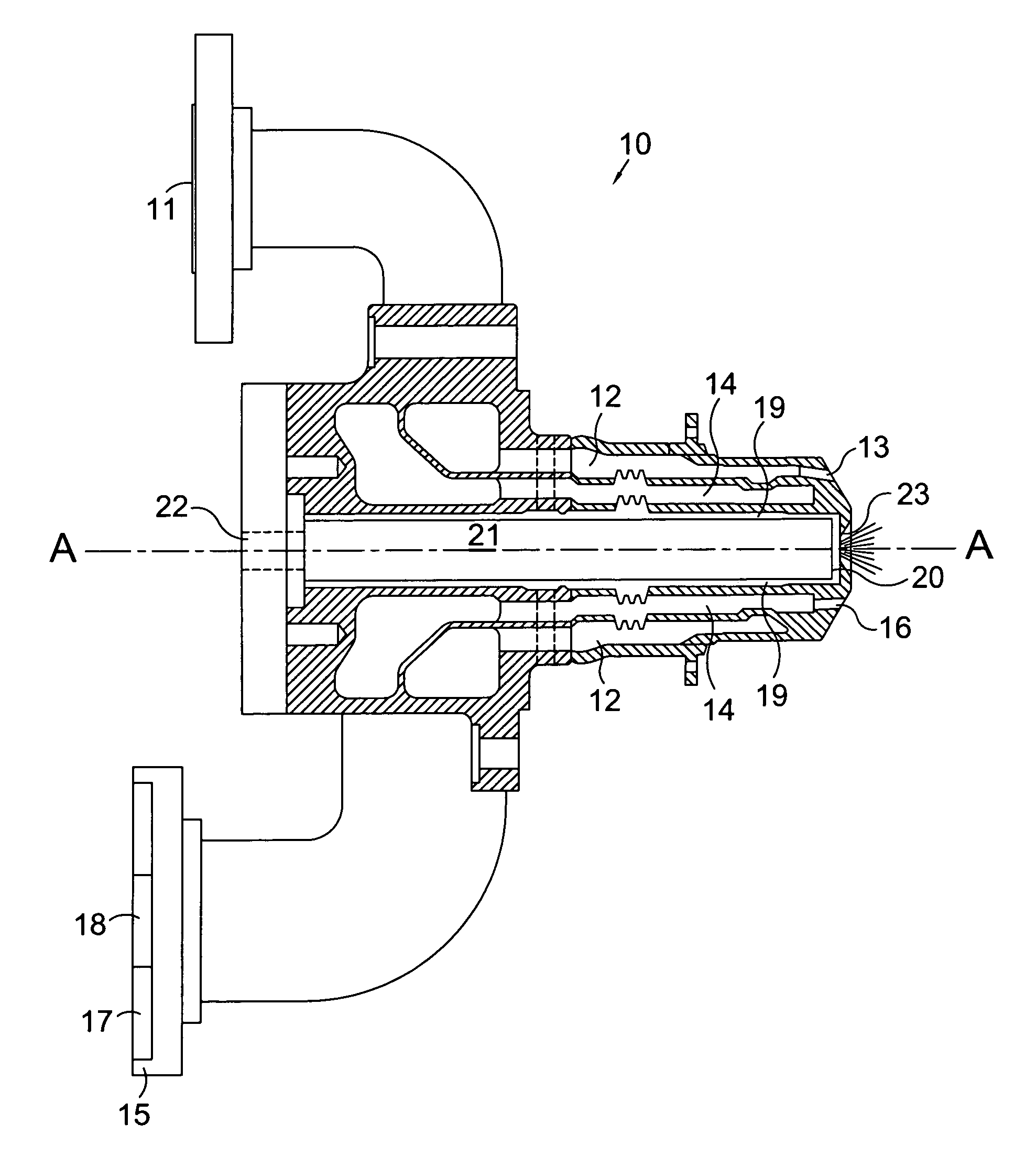
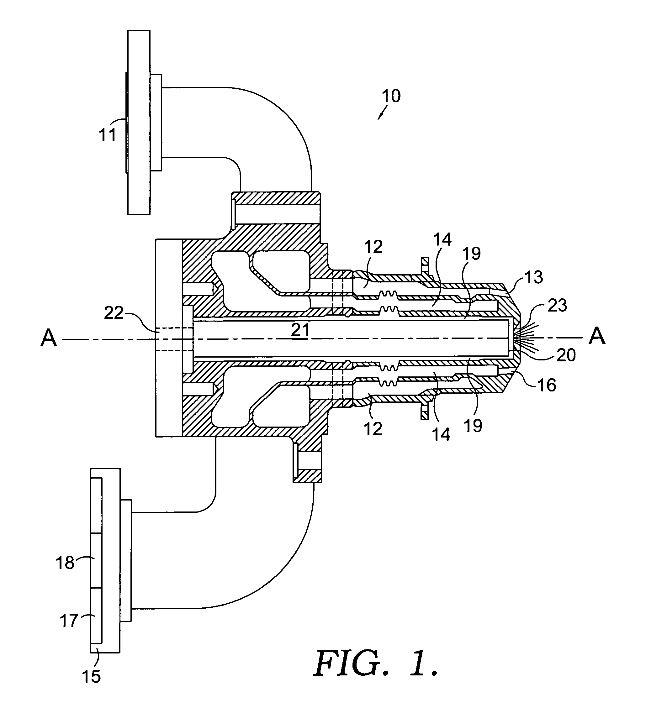
[0008]A fuel nozzle is provided having a first fuel passage and first fuel injection means, a second fuel passage and second fuel injection means, an air passage and air injection means, and a steam passage and steam injection means. In the preferred embodiment, the second fuel passage is located along the nozzle centerline with the air passage radially outward of the second fuel passage, and the steam passage radially outward of the air passage. Lastly, the first fuel passage is located radially outward of the steam passage. The steam passage is supplied with steam by a steam inlet that is connected to a steam manifold where the steam manifold supplies steam to each fuel nozzle. In order to control the steam flow to the fuel nozzle, a meterplate having at least one metering hole of constant diameter is placed at the steam inlet. The meterplate, in conjunction with the steam passage geometry and steam injection means, serves to regulate the pressure drop of the steam as well as the velocity of the steam. Controlling the pressure drop and velocity allows the operator to minimize the mal-distribution effects within a single combustor or between multiple combustors and reduce sensitivity to upstream steam supply variations, each of which reduce potentially damaging combustion dynamics. A further advantage of the present invention relates to the reduction of the exhaust gas temperature spread.
[0009]Typically, exhaust gases can vary by as much as 80 degrees Fahrenheit between adjacent combustors, thereby exposing the turbine to varying inlet temperatures, causing thermal distress to the vanes and blades. By maintaining better control over the steam flow for each combustor, such that each combustor receives the required amount of steam to match the fuel flow rate, variance in combustor flame temperature is reduced by as much as 50%.
[0010]It is an object of the present invention to provide a fuel nozzle capable of dual fuel injection and steam injection, where the steam is injected uniformly into a combustor.
[0011]It is another object of the present invention to reduce combustion dynamics to a combustor containing a fuel nozzle capable of dual fuel injection and steam injection.
[0012]It is yet another object of the present invention to disclose a method of providing uniform steam flow to a plurality of fuel nozzle assemblies about a gas turbine engine.

Problems solved by technology

Typically, exhaust gases can vary by as much as 80 degrees Fahrenheit between adjacent combustors, thereby exposing the turbine to varying inlet temperatures, causing thermal distress to the vanes and blades.

Method used


Image

  • Apparatus and method for improving combustion stability
  • Apparatus and method for improving combustion stability

Examples


Embodiment Construction

[0015]Referring to FIG. 1, a fuel nozzle assembly in accordance with the present invention is shown in cross section. Fuel nozzle assembly 10 includes a first fuel inlet 11 in fluid communication with a first fuel passage 12 and a first fuel injection means 13, such that a first fuel is supplied to a combustor. Located radially inward from first fuel passage 12 is a steam passage 14 that receives steam from a steam inlet 15 and directs it to a steam injection means 16 for supplying steam to a combustor. Steam flow to nozzle assembly 10 is regulated at steam inlet 15, preferably by a meterplate 17 that is fixed to steam inlet 15 and contains at least one metering hole 18 having a constant diameter. In the preferred embodiment, a single metering hole having a diameter of at least 0.25 inches is utilized, however multiple metering holes can be used in place of a single hole if desired. Meterplate 17 and metering hole 18 create an obstruction in the steam flow that reduces the fluid vel...


PUM


Abstract

A fuel nozzle for use in a gas turbine combustor is provided having the capability of injecting multiple fuel types as well as steam for NOx reduction. Combustion dynamics within a combustor due to the mal-distribution of steam are controlled by the placement of a meterplate at the steam inlet, such that the meterplate reduces steam velocity and increases steam pressure drop. A higher pressure drop reduces the sensitivity of the combustion process to upstream steam supply variations. A method for providing uniform steam flow to a plurality of fuel nozzle assemblies about a gas turbine engine is also disclosed.

Description

BACKGROUND OF THE INVENTION[0001]1. Field of the Invention[0002]The present invention relates to fuel nozzles for gas turbine combustors and more specifically to fuel nozzles that utilize multiple fuel types and have the capability for steam injection to control emissions of oxides of nitrogen (NOx).[0003]2. Description of Related Art[0004]Land based gas turbine engines typically include at least one combustor for producing hot gases necessary to drive the turbine section of the engine. Each combustor contains at least one fuel nozzle for injecting fuel to mix with compressed air from the engine compressor and react to form the hot gases. Depending on engine operating requirements and environmental issues, the fuel nozzles can inject multiple fuel types, including gaseous fuel and liquid fuel. In recent years, reductions in emissions levels, especially with respect to NOx and carbon monoxide (CO), have been the main focus of equipment manufacturers, especially since the operation of...

Claims


Application Information

Patent Timeline
IPC IPC(8): F02C3/30F23R3/36F23D17/00F23L7/00
CPCF23D17/002F23R3/36F23L7/005F23D2204/10F23L2900/07009
Inventor MARTLING, VINCENT C.LEAHY, JR., JAMES H.
Owner ANSALDO ENERGIA IP UK LTD
Learn More