Suspension system for suspending a wheel having a motor therein

a suspension system and wheel technology, applied in the direction of braking discs, electric devices, cycle equipment, etc., can solve the problems of reducing the cooling characteristic of the braking system, the inability to achieve the intrinsic functions of the suspension system, etc., to achieve the effect of reducing reducing the degree of flexibility in design, and minimizing the length of the path

Inactive Publication Date: 2010-06-15
TOYOTA JIDOSHA KK
View PDF18 Cites 33 Cited by
  • Summary
  • Abstract
  • Description
  • Claims
  • Application Information

AI Technical Summary

Benefits of technology

[0007]According to this aspect of the present invention, providing the mounting portion of the suspension arm on the inner surface of the cylindrical member increases the degree of flexibility in designing the suspension arms and an alignment change of the suspension system. This enables giving the suspension system desired functions that are intrinsically required for the suspension system, even with the suspension system in which a motor is disposed within the wheel.
[0008]Advantageously, the suspension system may include a bearing that is arranged between the cylindrical member and the rotor and outboard of the rotor. This arrangement enables minimizing the length of the path over which various loads, such as up-and-down loads, transverse loads, and back-and-forth loads applied to the wheel, a braking torque of a braking system, and a driving torque of the motor, are transferred. This allows miniaturization of the components over the load-transferring path and thus cost reduction.
[0009]Advantageously, the suspension system may include a sealing that is arranged between the cylindrical member and the rotor and inboard of the rotor; and a sealing second bearing that is arranged between the cylindrical member and the rotor and adjacent to the sealing. This arrangement stabilizes and improves a sealing characteristic between the cylindrical member and the rotor of the motor, because the arrangement in which the second bearing is provided adjacent to the sealing can reduce the variance of the engaging margin of the sealing lip due to deformations of the cylindrical member and the rotor portion of the motor. It is noted that the second bearing may be a deep groove small bearing rather than a bearing that serves a function of carrying loads applied to the wheel, such as a bearing disposed on the outboard side of the motor.
[0010]Further, a brake disk may be connected to the rotor in such a manner that a disk surface of the brake disk is located within the space defined by the cylindrical member. With this arrangement, airflow generated through the space facilitates the cooling efficiency of the brake disk surface and the rotor. Further, disposing the brake disk surface outboard of the vehicle with respect to the mounting positions of the suspension arms allows the ideal positioning of the suspension arms and the braking system within the wheel.

Problems solved by technology

Thus, with such arrangements, functions required intrinsically for a suspension system cannot be achieved.
Furthermore, this arrangement lowers a cooling characteristic of the braking system.

Method used


Image

  • Suspension system for suspending a wheel having a motor therein
  • Suspension system for suspending a wheel having a motor therein
  • Suspension system for suspending a wheel having a motor therein

Examples


Embodiment Construction

[0014]Hereafter, the preferred embodiments according to the present invention are explained with reference to the drawings.

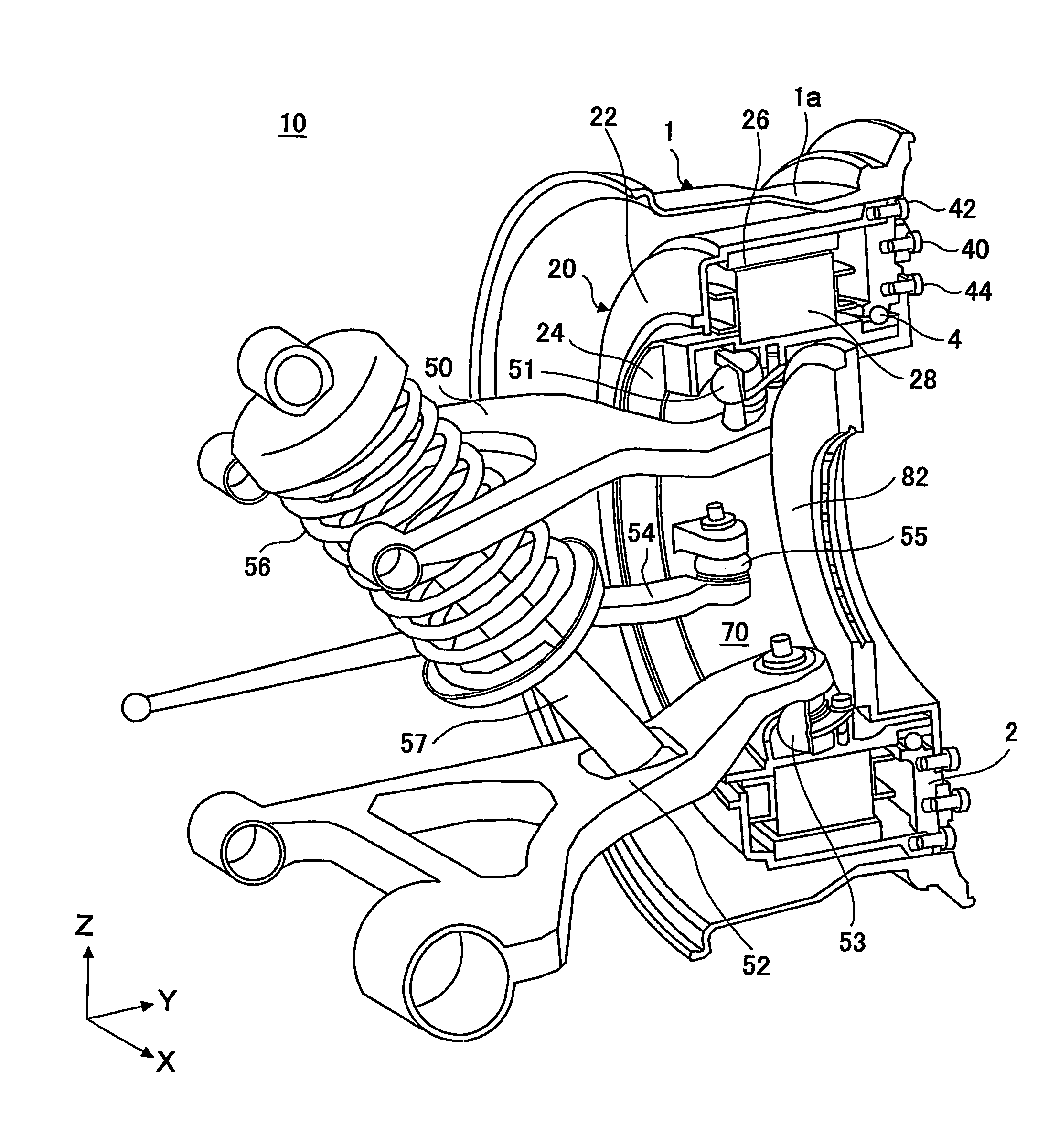
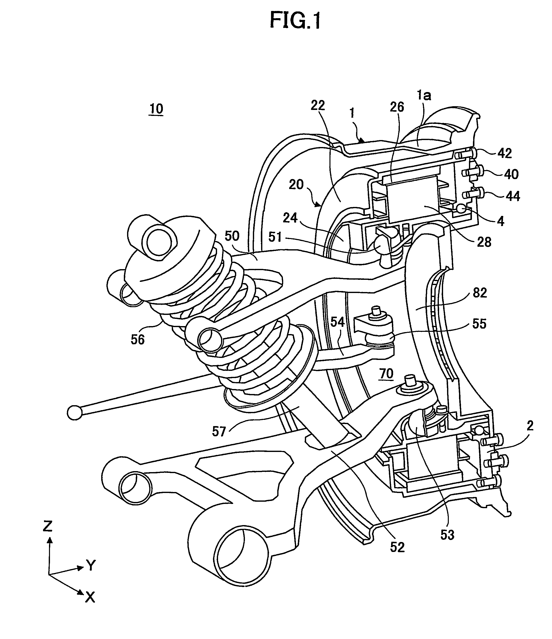
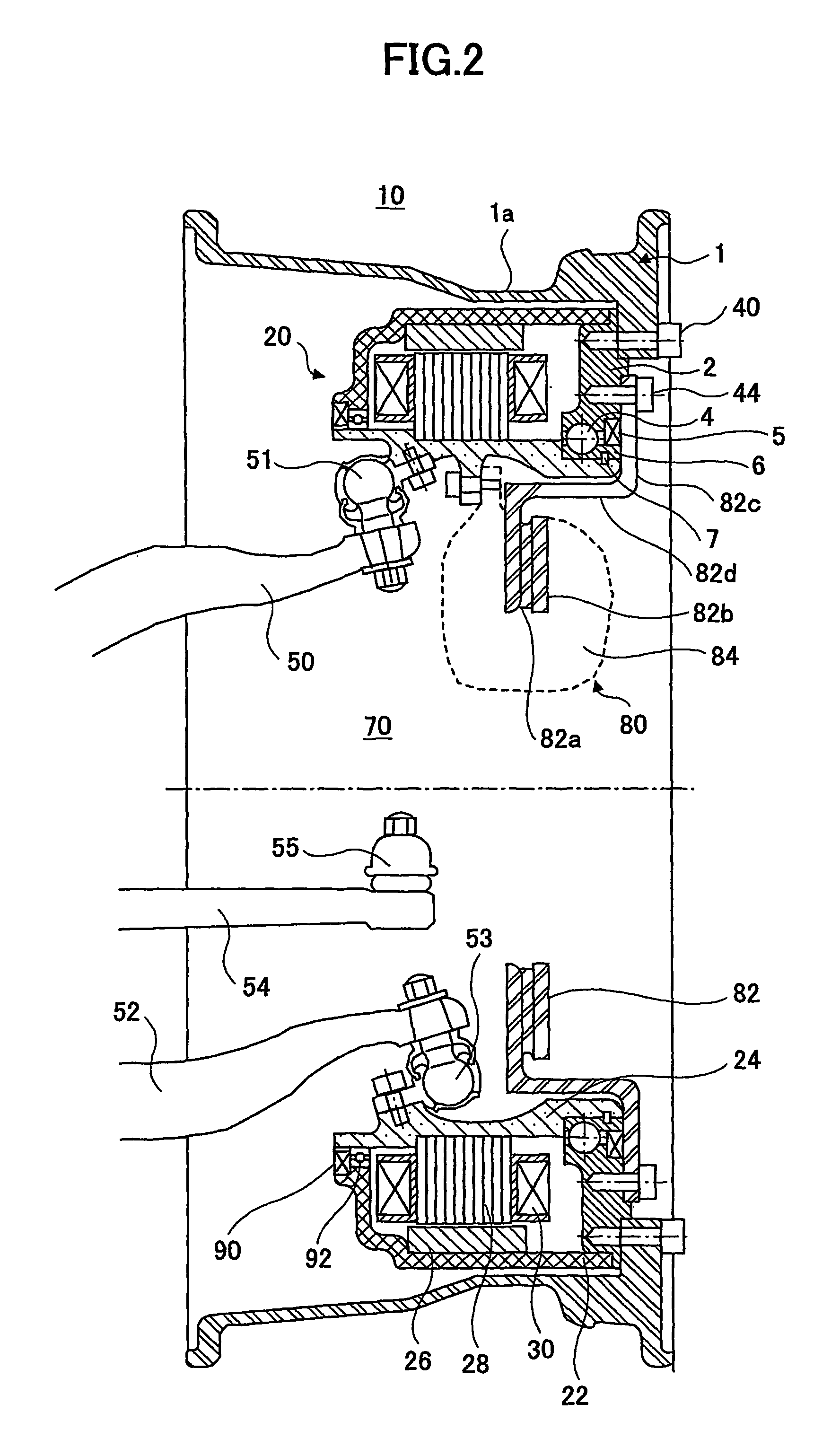
[0015]FIG. 1 is a diagram showing a suspension system 10 according to an embodiment of the present invention by a sectional structure in part and in perspective view seen from an inboard side of a vehicle. FIG. 2 is a cross-sectional view of a main part of the suspension system 10 shown in FIG. 1.

[0016]The suspension system according to this embodiment has a motor 20 for driving a wheel. One of the motors 20 is provided in every wheel of the vehicle. Explanation is made below for only one wheel, since there is substantially no difference in arrangement between the wheels. However, it is noted that the arrangement according to this embodiment may be applied to only front wheels or only rear wheels.

[0017]Referring to FIG. 1 and FIG. 2, the motor 20 is disposed inside a wheel 1, as further discussed below. The motor 20 has a ring-like shape that corresponds to an i...


PUM


Abstract

A suspension system 10 for a vehicle for suspending a wheel 1 is disclosed. An outer rotor type motor 20 is provided within the wheel 1. The motor 20 has a stator (28, 30) provided on an outer surface of a cylindrical member 24 that defines space 70 open to at least an inboard side of the vehicle, and a rotor (22,26) rotatably supported by the cylindrical member 24. The wheel 1 receives the motor 20 and is connected to the rotor (22,26). The mounting portions of suspension arms (50,52,54) are provided on an inner surface of the cylindrical member 24.

Description

TECHNICAL FIELD[0001]The present invention relates to a suspension system for use in a vehicle, which suspends a wheel inside which a motor for driving the wheel is provided.BACKGROUND ART[0002]JP2-120198 A discloses a suspension system for use in a vehicle, wherein a motor for driving the wheel is provided inside the wheel. In this suspension system, an outer portion of the motor, which corresponds to the rotor portion of the motor, is connected to a wheel disk, while an inner portion of the motor, which corresponds to the stator portion of the motor, is supported so as not to rotate with respect to a vehicle body.[0003]In the conventional suspension system as disclosed in JP2-120198 A, there is no other choice but to dispose a braking system or a suspension arm on the central side of the vehicle with respect to the motor, because the motor occupies a large amount of space inside the wheel and substantially no available space remains around the center of the wheel due to existence ...

Claims


Application Information

Patent Timeline
Patent Type & Authority Patents(United States)
IPC IPC(8): B60K1/00B60B35/14B60G7/00B60B35/18B60G3/20B60K7/00F16D55/02F16D65/12H02K21/22
CPCB60G3/20B60K7/0007B60G2200/144B60K2007/0092B60K2007/0038B60L7/24B60L2220/44B60L2270/145B60K7/00
Inventor MURATA, SATOSHI
Owner TOYOTA JIDOSHA KK
Why Eureka
Try Eureka