Camera viewer device

a viewer device and camera technology, applied in the field of camera viewer devices, can solve the problems of unfavorable decision-making about image composition by feeling, unfavorable decrease of visual recognition of the image of the subject displayed in the display panel, and reduced image recognition effect, so as to achieve easy attachment and removal

Inactive Publication Date: 2007-02-01
RICOH KK
View PDF2 Cites 4 Cited by
  • Summary
  • Abstract
  • Description
  • Claims
  • Application Information

AI Technical Summary

Benefits of technology

[0031] According to the second aspect of the present invention, the camera viewer device can be used as a low angle finder and as a direct-viewing type finder, external light is prevented from entering the finder, the image of the subject can be observed in a magnified state, and the finder can be assembled without increasing the number of parts.
[0032] According to the preferred embodiment of the second aspect to the present invention, the camera viewer device can be easily attached and detached relative to the camera body.

Problems solved by technology

Consequently, it is unfavorably difficult to decide an image composition by feeling.
Thus, the external light is likely to enter eyes upon reflection with the mirror, so that the contrast of the image of the subject displayed in the display panel becomes relatively lower to unfavorably decrease visual recognition of the image of the subject displayed in the display panel.
There is similar inconvenience in case that the image of the subject displayed in the display panel is directly observed without the mirror.

Method used


Image

  • Camera viewer device
  • Camera viewer device
  • Camera viewer device

Examples


Embodiment Construction

[0046] In the following, preferred embodiments of the camera viewer device according to the present invention for a digital camera will be explained with reference to the attached drawings.

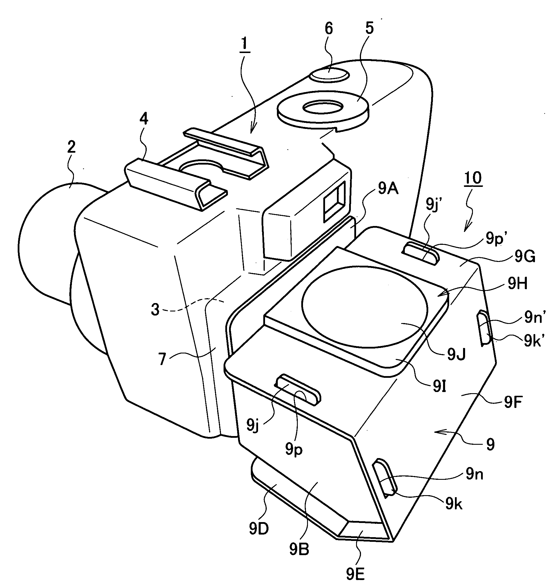
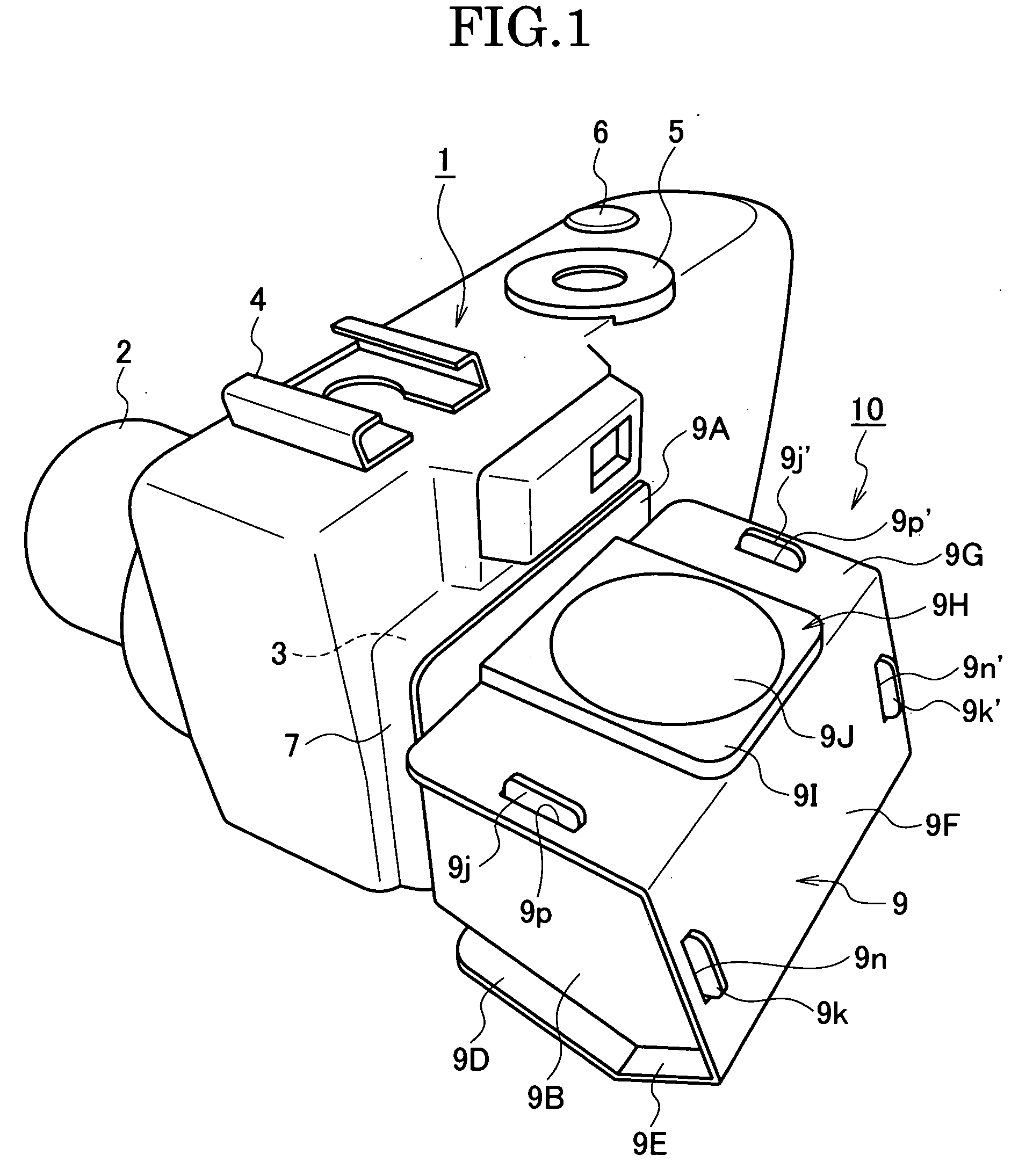
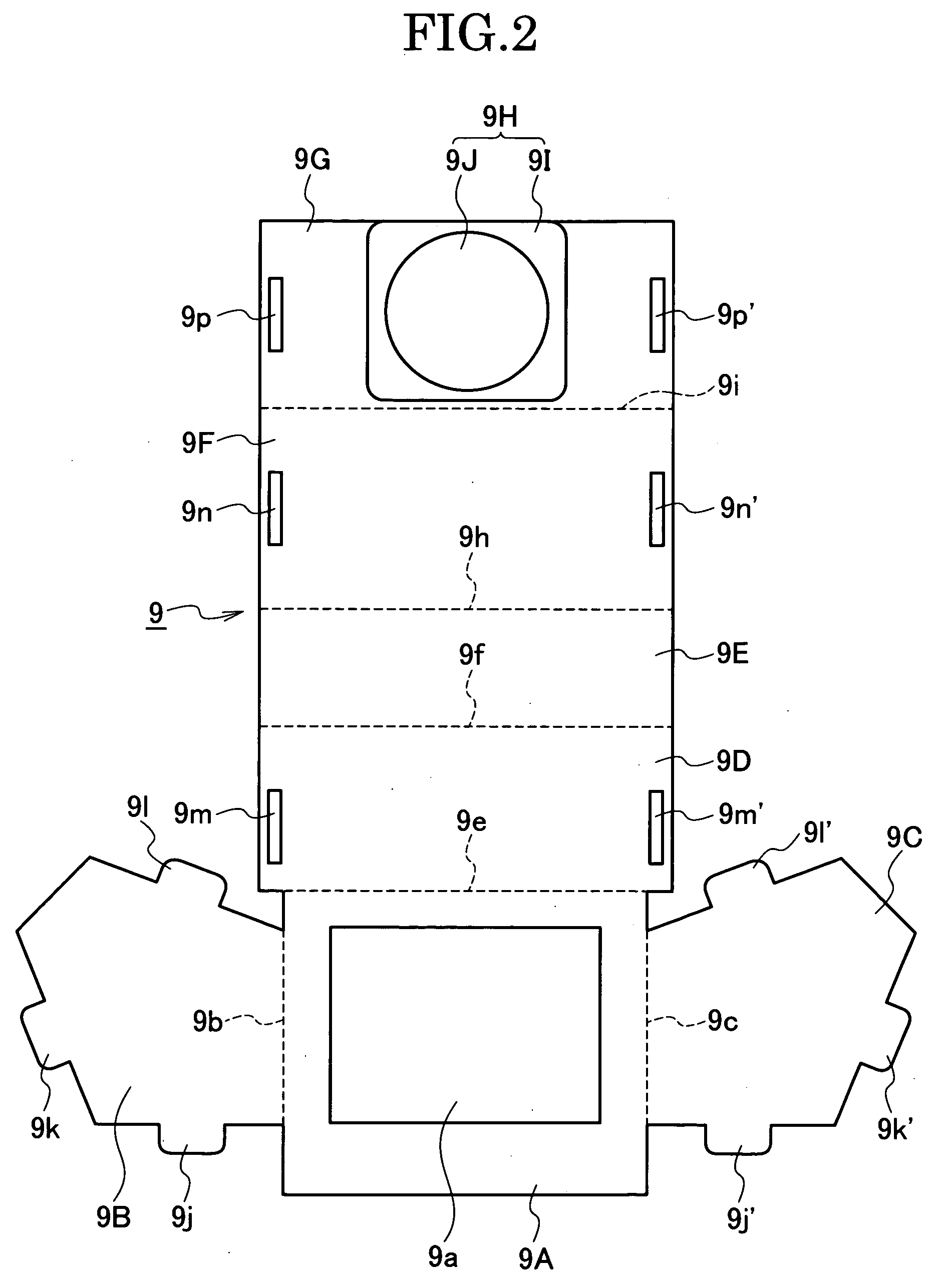
[0047]FIG. 1 is an external view of a first embodiment of a camera viewer device according to the present invention attached to a digital camera. FIG. 2 and FIG. 3 are developed plane views of the camera viewer device according to the present invention. FIG. 4 is an external view of the camera viewer device according to the present invention which is assembled in the form of the first configuration.

[0048] In FIG. 1, a reference numeral 1 denotes a camera body, and a lens barrel 2 is provided at a front face portion of the camera body 1. A liquid crystal type display panel 3 having an almost rectangular shape is provided at a back face portion of the camera body 1. A connector 4 for an external strobe device, a mode dial 5 and a shutter button 6 are provided at an upper portion of the camera body...


PUM


Abstract

A camera viewer device, includes an assembling sheet member to be developed and changed in shape between a first configuration: box-shaped angle finder and a second configuration: direct viewing finder. The sheet member includes first and second mirror wall portions with first and second inner mirrors, an attachment wall portion to be attached to the back face side of a camera body, and an upper wall portion. When the sheet member is assembled in the first configuration, the first mirror reflects an image of a subject in a display panel on the back face of the camera body and downwardly projects the image of the subject, the second mirror upwardly projects the projected image, a window portion of the attachment wall portion is opposed to the display panel, and the window portion of the upper wall portion is opposed to the second mirror wall portion to look into the interior of the assembled sheet member through the window portion of the upper wall portion.

Description

CONVENTION PRIORITY CLAIMED [0001] The convention priority of Japanese patent application No. 2005-218394 filed on Jul. 28, 2005 is claimed in this application. The entire contents of the Japanese patent application No. 2005-218394 are incorporated herein by reference. BACKGROUND OF THE INVENTION [0002] (1) Field of the Invention [0003] The present invention relates to an improvement on a camera viewer device, more particularly, on a viewer device for a liquid display type digital camera. [0004] (2) Related Art Statement [0005] According to conventional camera viewer devices, for example, viewer devices for liquid display type digital cameras are known, which enable an image of a subject displayed in a display panel provided at a back face of a camera body to be observed from vertical and lateral directions through a mirror disposed at a rotatable support member (See JP-A 2004-297561). [0006] However, since a single mirror is used in such a conventional viewer device for the liquid ...

Claims


Application Information

Patent Timeline
Patent Type & Authority Applications(United States)
IPC IPC(8): G03B17/18
CPCG03B13/02H04N5/23293H04N5/2251H04N23/50
Inventor WATANABE, TATSUYA
Owner RICOH KK
Why Eureka
Try Eureka