
Dynamic hip stabilizer

a hip stabilizer and dynamic technology, applied in the field of hip stabilizers, can solve the problems of patient movement, pillow is rarely capable of preventing postoperative dislocation, and is too wide and moveable for patients, so as to reduce the risk of hip dislocation

Inactive Publication Date: 2007-02-01
DRENNAN DENIS BURKE
View PDF22 Cites 47 Cited by
  • Summary
  • Abstract
  • Description
  • Claims
  • Application Information

AI Technical Summary

Benefits of technology

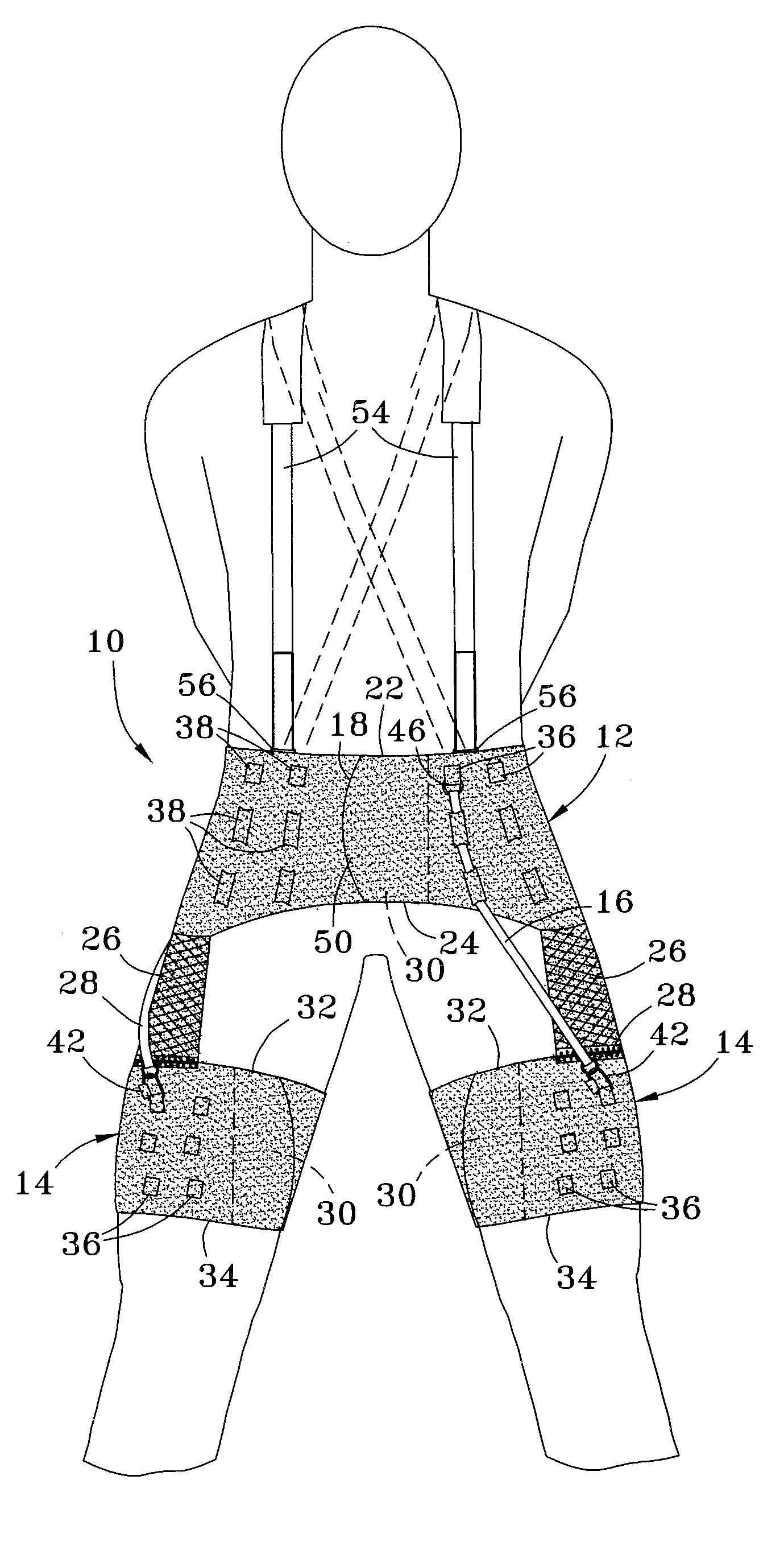
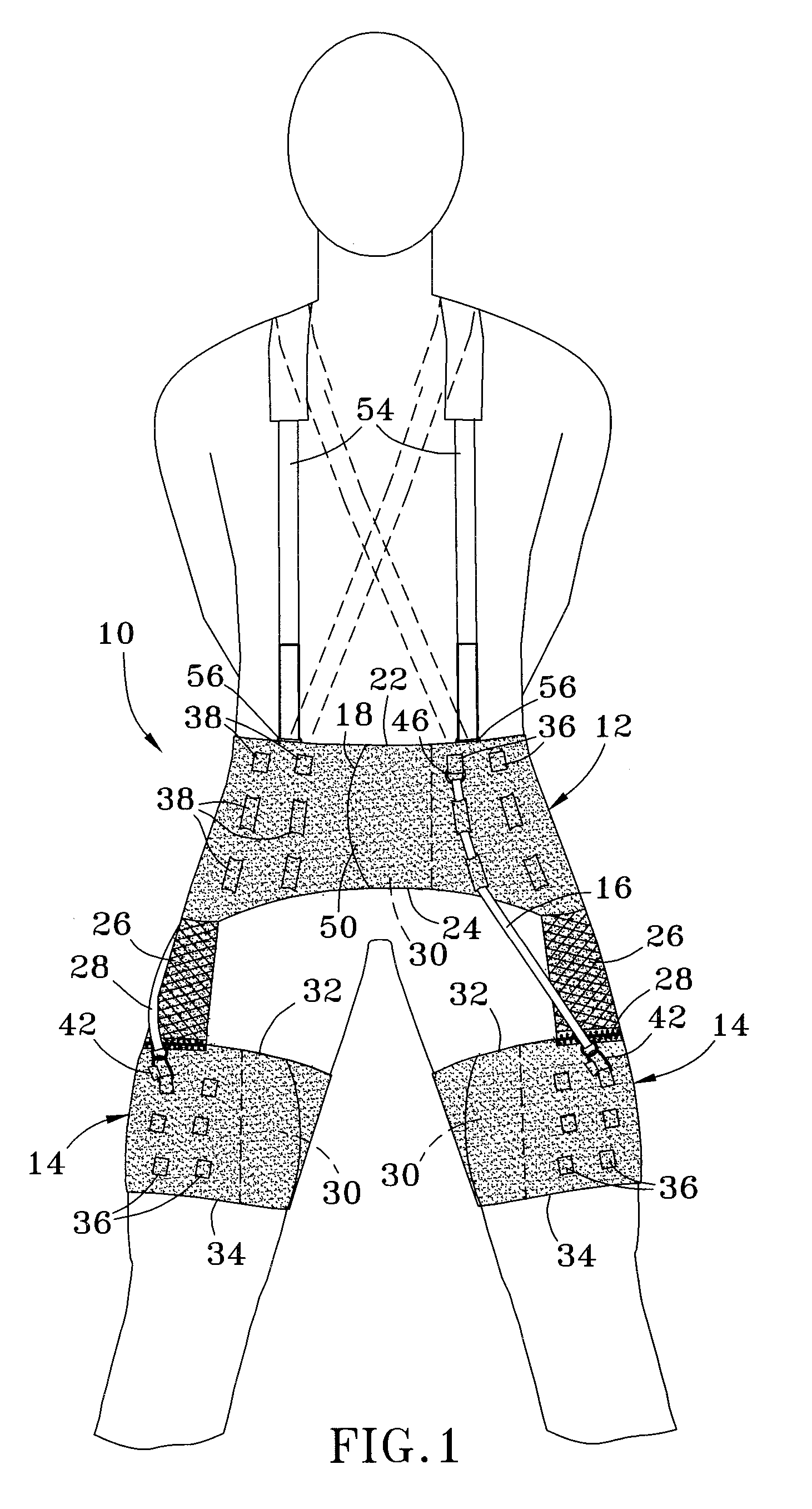
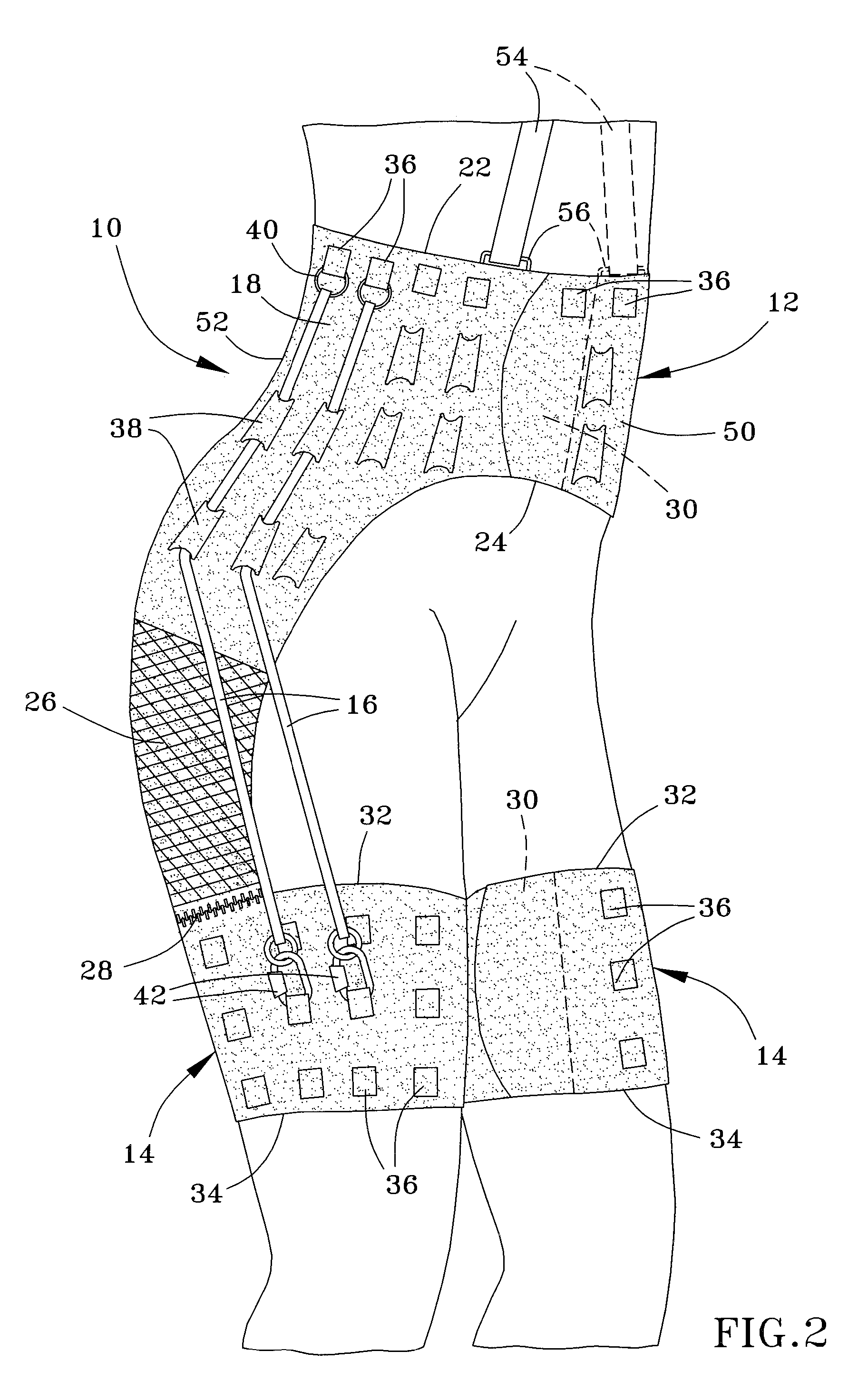
"The present invention is a dynamic hip stabilizer that reduces the risk of hip dislocations, including postoperative and recurrent traumatic hip dislocations. It consists of a pelvic girdle, thigh cuff, and elastic tensile force generating elements. The elastic tensile force holds the wearer's thigh to the pelvis with sufficient tension to control excessive adduction, flexion or extension, and provide hip stability by controlling and modifying certain hip motions. The stability and proper positioning of the girdle is enhanced by the action of elements that limit movement of the girdle and provide support to the lower back of the wearer."

Problems solved by technology

Conventional pillows are too moveable and not wide enough to give consistent abduction, and undesirably allow the patient to move about.
As a result, a pillow is rarely capable of preventing postoperative dislocation because it does not move with the patient who rolls over, or when the patient sits at the side of the bed or is being transferred to a wheel chair.
Foam abduction pillows are clumsy and require considerable nursing effort to roll a patient from side to side.
A significant shortcoming of hip spica casts is the risk of prolonged stiffness because of the lack of all motion at the hip for many weeks.
Though single hip spica abduction braces can be worn in bed and while the patient sits and is being transferred, form-fit plastic abdominal and thigh portions of the brace often do not fit well, and allow many patients to rotate, putting the hip at risk.
These braces also often allow some adduction and internal rotation, which is a significant risk to hip stability.
However, if not maintained in its fully abducted position, this type of brace allows for adduction to neutral and flexion is uncontrolled.
In addition, this type of brace cannot be worn during patient bed-to-wheelchair transfers or during gait training.

Method used


Image

  • Dynamic hip stabilizer
  • Dynamic hip stabilizer
  • Dynamic hip stabilizer

Examples


Embodiment Construction

[0016]FIGS. 1 through 5 show a dynamic hip stabilizer 10 in accordance with the present invention. The hip stabilizer 10 is shown as including a pelvic girdle 12 and two thigh cuffs 14. The girdle 12 is shown as being elastically interconnected to each thigh cuff 14 with elastic cables 16. The cables 16 are shown connected to the girdle 12 and the thigh cuffs 14 so that, when the hip stabilizer 10 is worn, the cables 16 cooperate to generate an elastic tensile force between the girdle 12 and the cuffs 14. As will be discussed in more detail below, a preferred aspect of the invention is that this elastic tensile force serves to hold the wearer's thigh to the wearer's pelvis with sufficient tension to prevent hip dislocations by controlling excessive adduction, flexion and / or extension, control excessive internal or external rotation, and promote hip stability by controlling and modifying certain hip motions through increasing tension as the extremes of a particular motion are approac...


PUM


Abstract

A dynamic hip stabilizer utilized to reduce the risk of postoperative and recurrent traumatic hip dislocations. The hip stabilizer includes a pelvic girdle, at least one thigh cuff, and one or more elements for generating an elastic tensile force between the girdle and cuff. The girdle has an upper portion configured for defining an upper opening for the wearer's waist, a lower portion configured for defining a lower opening for the wearer's hips, and a posterior portion configured for engaging the wearer's lower back. The hip stabilizer further includes one or more elements for engaging the wearer's shoulders to limit movement of the girdle toward the thigh cuffs caused by the elastic tensile force, and one or more elements for stiffening the posterior portion of the girdle.

Description

CROSS REFERENCE TO RELATED APPLICATIONS [0001] This is a continuation-in-part patent application of co-pending U.S. patent application Ser. No. 10 / 604,993, filed Aug. 29, 2003, which claims the benefit of U.S. Provisional Application No. 60 / 319,519, filed Sep. 4, 2002. The contents of these prior applications are incorporated herein by reference.BACKGROUND OF THE INVENTION [0002] The present invention relates to devices utilized to reduce the risk of postoperative hip dislocations and recurrent traumatic hip dislocations. More particularly, this invention relates to a dynamic hip stabilizer with a combination of components that generate tensile (tensional) forces capable of holding a patient's thigh to the patient's pelvis, preferably with enough tension to control excessive adduction, flexion or extension, control excessive internal or external rotation, provide hip stability by controlling and modifying certain hip motions through increasing tension as the extremes of a particular...

Claims


Application Information

Patent Timeline
Patent Type & Authority Applications(United States)
IPC IPC(8): A61F5/00A61F5/01A63B21/055A63B23/04
CPCA61F5/0193A63B21/0004A63B21/00065A63B21/0407A63B21/0557A63B2208/0204A63B21/1419A63B21/1423A63B21/1449A63B23/0482A63B21/1411A63B21/4011A63B21/4005A63B21/4009A63B21/4025
Inventor DRENNAN, DENIS BURKE
Owner DRENNAN DENIS BURKE
Learn More