Pendulum bow sight

a pendulum bow and sight technology, applied in the field of sighting devices, can solve the problems of many bow sights falling short of ideal, obscuring some parts of targets, and increasing the chances of obscuring potential targets

Active Publication Date: 2007-02-08
BRADBOW
View PDF33 Cites 32 Cited by
  • Summary
  • Abstract
  • Description
  • Claims
  • Application Information

AI Technical Summary

Benefits of technology

[0011] The pendulum bow sight is a sight apparatus for an archery bow that provides a luminescent sighting element disposed within a field of view of an optic lens without obstructing the field of view used for sighting a target. The sight apparatus provides unobstructed viewing through a pendulum sight regardless of a bow elevation angle. The pendulum sight has a pivoting lens assembly, which is suspended by a supporting structure capable of being mounted to e.g., the riser of a bow. The bow sight lens assembly is freely rotatable about a pivot axis disposed across a region encompassed by the supporting structure. The pendulum bow sight provides independent horizontal and vertical adjustments of the sighting element for calibration that is good for up to thirty-five yards, and with any bow elevation angle.

Problems solved by technology

The problems include focusing on the prey through a sighting element in order to position the bow to shoot at the target.
However, many bow sights fall short of the ideal in that they often obscure some part of the target because the sighting elements employed have too much width or length.
Moreover, the more pins used as sighting elements, the more chances that a potential target will be obscured by one or more of the pins.
While these particular devices have met with some success, problems have been encountered with the use of pins for sighting elements.
The capability to view the target in an unobstructed manner is especially problematic on hilly terrain, or when there is an elevation difference between hunter and the hunted.
Conventional pendulum sights have been limited due to the fact that often sighting pins used in the pendulum obscure at least some portion of the target.

Method used


Image

  • Pendulum bow sight
  • Pendulum bow sight
  • Pendulum bow sight

Examples


Embodiment Construction

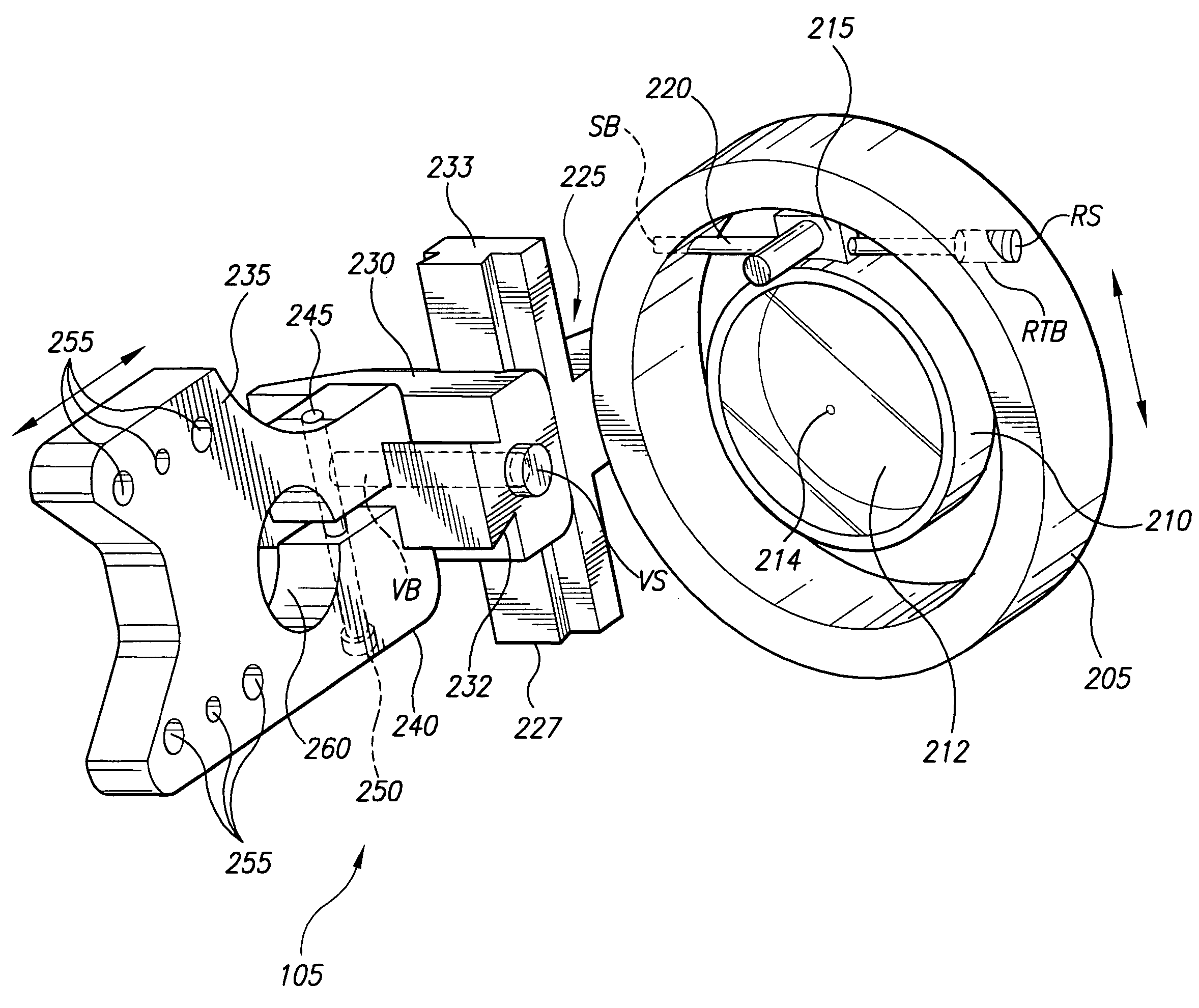
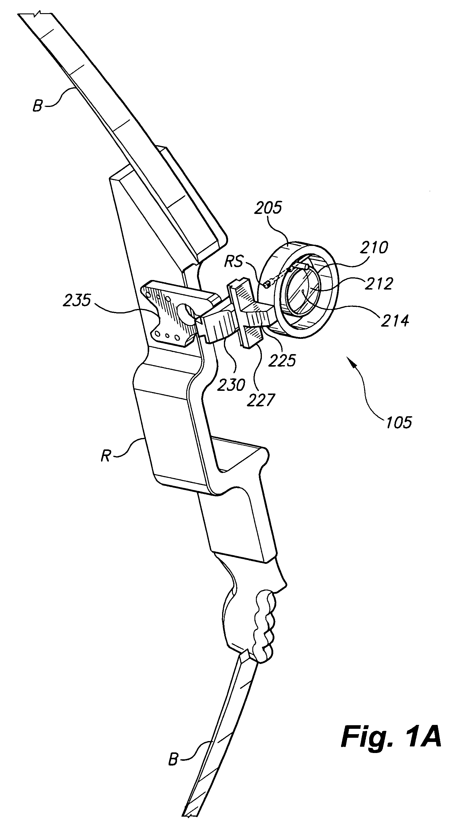
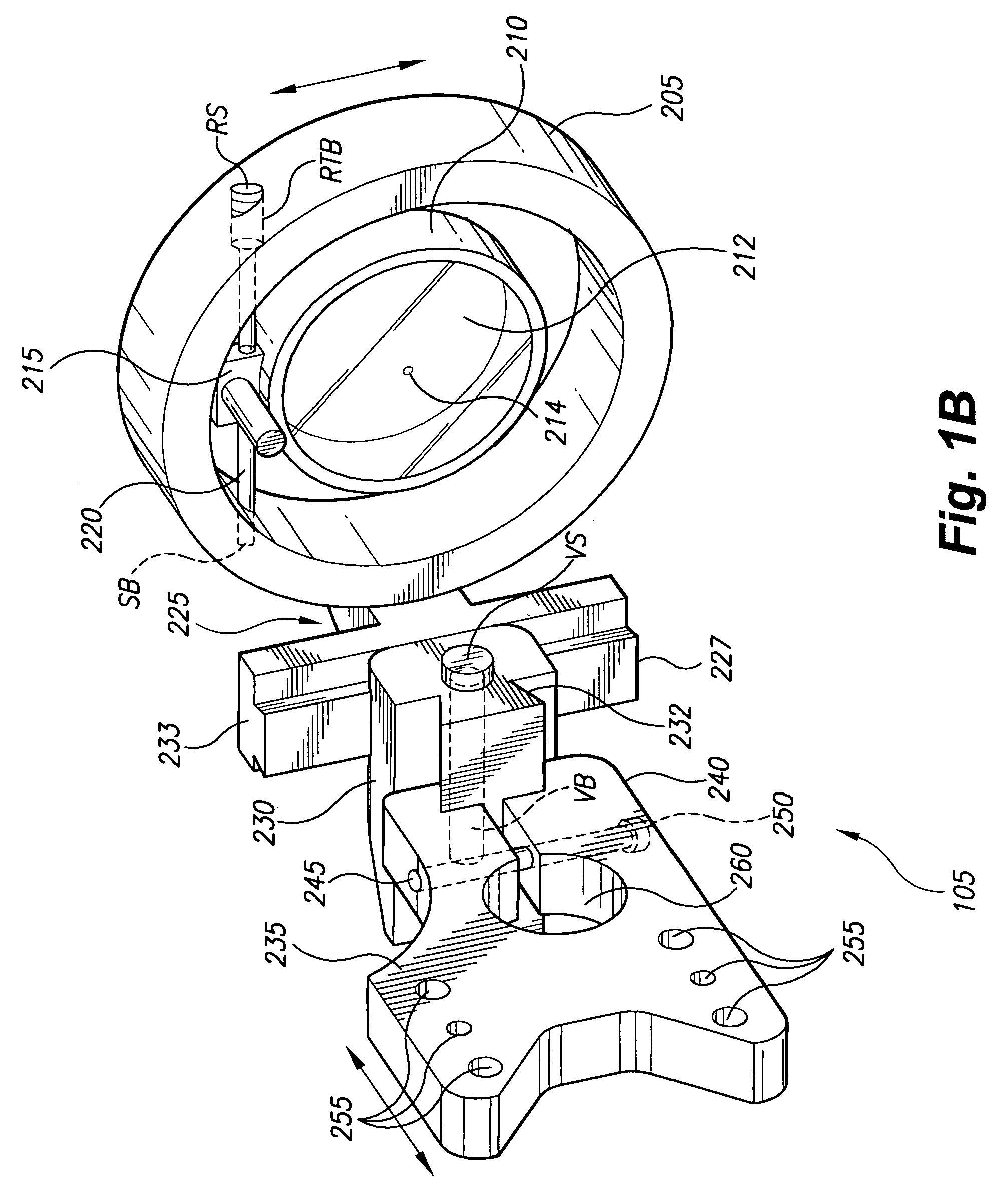
[0021] The present invention is a pendulum bow sight 105 capable of being mounted to a riser R of an archery bow B, as shown in FIG. 1A. The pendulum bow sight 105 includes a sight apparatus for an archery bow that provides a luminescent sighting element 214 disposed within a field of view of an optic lens 212 so that the field of view used for sighting a target is not obstructed.

[0022] The pendulum bow sight 105 provides the unobstructed view through the lens 212 regardless of a bow elevation angle. As shown in FIG. 1A, a lens assembly of the pendulum sight 105 comprises lens frame 210 and optical lens 212. It is also within the scope of the present invention to provide a frameless lens assembly. The luminescent sighting element 214 may be encapsulated in, or otherwise fixed to the center or other appropriate region of optic lens 212 so that it does not require a supporting pin. In other words, luminescent sighting element 214 is supported by the lens 212 and appears as a target s...


PUM


Abstract

The pendulum bow sight is a sight apparatus for an archery bow that provides a luminescent sighting element disposed without the use of supporting pins in a field of view of an optic lens without obstructing the field of view used for sighting a target. The sight apparatus provides unobstructed viewing through a pendulum sight regardless of a bow elevation angle. The pendulum sight has a pivoting lens assembly, which is suspended by a supporting structure capable of being mounted to e.g., the riser of a bow. The bow sight lens assembly is freely rotatable about a pivot axis disposed across a region encompassed by the supporting structure. The pendulum bow sight provides independent horizontal and vertical adjustments of the sighting element for calibration that is good for up to thirty-five yards, and with any bow elevation angle.

Description

CROSS-REFERENCE TO RELATED APPLICATION [0001] This application claims the benefit of U.S. Provisional Patent Application Ser. No. 60 / 705,493, filed Aug. 5, 2005. Additionally, this application claims the benefit of U.S. Provisional Patent Application Ser. No. 60 / 757,882, filed Jan. 11, 2006.BACKGROUND OF THE INVENTION [0002] 1. Field of the Invention [0003] The present invention relates to sighting devices for use with an archery bow, and more particularly to an archery pendulum bow sight that provides a sighting element configured for an unobstructed view of the target in a sighting field of view. [0004] 2. Description of the Related Art [0005] Users of archery bow and arrow systems for hunting usually must deal with several problems to consistently kill prey. The problems include focusing on the prey through a sighting element in order to position the bow to shoot at the target. Bow sights are normally used on the bow to aid the hunter in properly aiming the arrow at the intended ...

Claims


Application Information

Patent Timeline
Patent Type & Authority Applications(United States)
IPC IPC(8): F41G1/467
CPCF41G1/467
Inventor BRADLEY, JOHN K.BOWEN, BRIAN T.
Owner BRADBOW
Why Eureka
Try Eureka