Antenna device

a technology of antenna and antenna body, applied in the direction of antenna details, antennas, electrical equipment, etc., can solve the problems of unomnidirectional antenna radiation pattern, high frequency operation, phone efficiency drop, etc., and achieve the effect of improving radiation character

Inactive Publication Date: 2007-02-08
BENQ CORP
View PDF4 Cites 7 Cited by
  • Summary
  • Abstract
  • Description
  • Claims
  • Application Information

AI Technical Summary

Benefits of technology

[0008] Accordingly, it is an object of the present invention to provide an antenna device which has a metal feeding line feeding from the center part of the printed circuit board of the mobile unit so as to have a better radiation character as transmission at high frequency for the antenna device.

Problems solved by technology

When the spiral antenna is used for shell phones, there occurred some problems in high frequency operation.
Especially, when operating at DCS frequency band (range from 1710 MHz to 1880 MHz), the shell phone who use this kind of antenna may cause an un-omnidirectional antenna radiation pattern because of uneven surface current distribution on the grounding plane 22.
The defect of transmission angle of the antenna device locates on the left side of the shell phone because of the defect of radiation pattern occurs in y axis of y-z plane and further causes the efficiency drop of the phone.

Method used


Image

  • Antenna device
  • Antenna device
  • Antenna device

Examples


Embodiment Construction

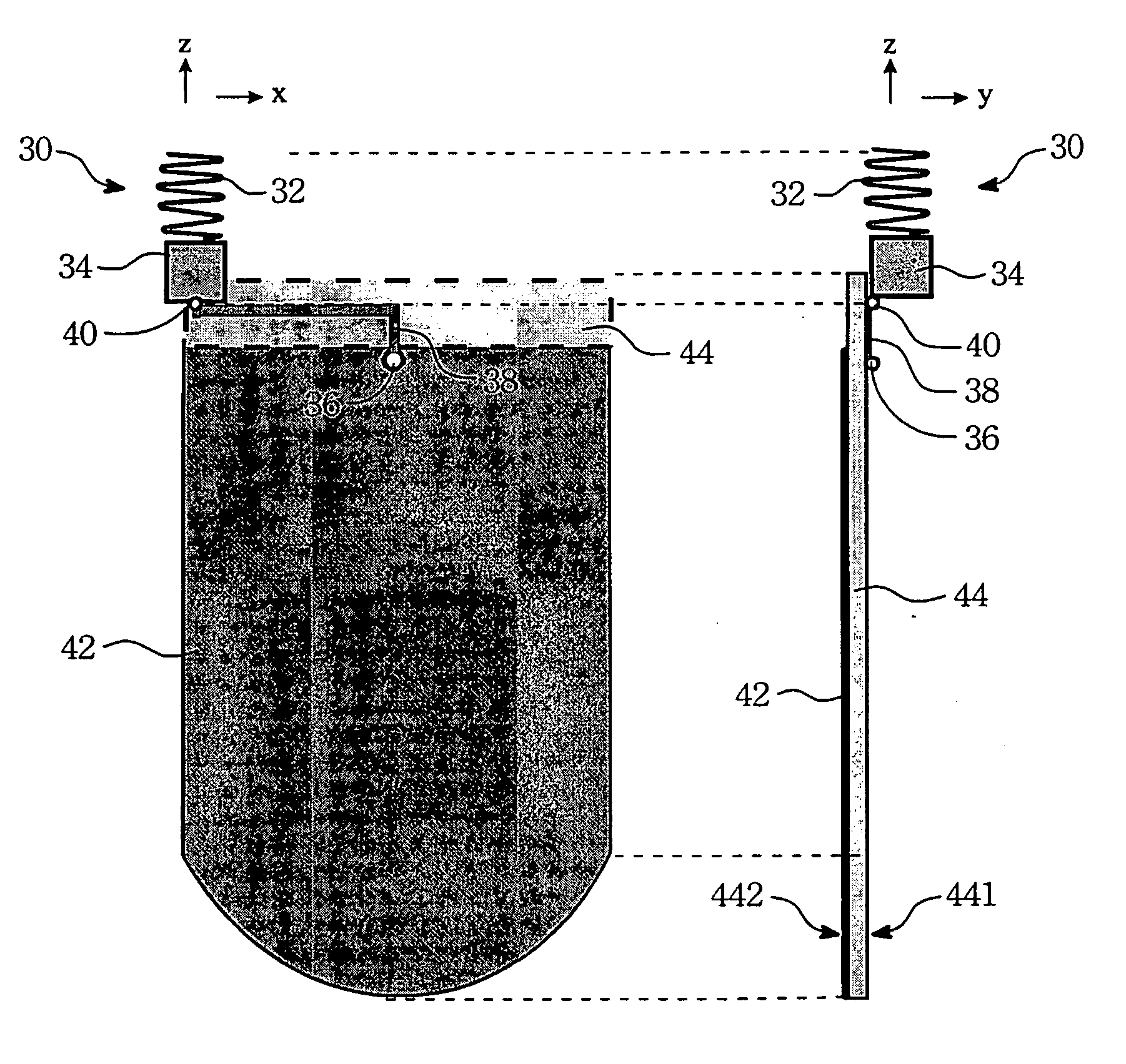
[0018] The invention disclosed herein is to provide an antenna device, and more particularly to provide an antenna device used in mobile unit. In the present invention, it is provided an antenna device which has a metal feeding line feeding from the center part of the printed circuit board (PCB) of the mobile unit so as to have a better radiation character as transmission at high frequency for the antenna device. In the following description, numerous details are set forth in order to provide a thorough understanding of the present invention. It will be appreciated by one skilled in the art that variations of these specific details are possible while still achieving the results of the present invention. In other instance, well-known components are not described in detail in order not to unnecessarily obscure the present invention.

[0019] Referring to FIG. 3, a schematic view illustrates an antenna device with the relating mobile unit (e.g. cell phone) in accordance with the preferre...


PUM


Abstract

An antenna device is for a mobile unit to transmit/receive signals, and the mobile unit comprises a printed circuit board which is mounted with a signal processing circuit for processing the signals, the antenna device comprises an antenna body, a metal feeding line, and a ground metal layer. The antenna body is mounted on one side of the mobile unit for transmitting/receiving signals. The metal feeding line made on the upper surface of the printed circuit board, one end of the metal feeding line is connected to the antenna body and the other end of the metal feeding line is in connection with the signal processing circuit from the center part of an edge of the printed circuit board. The ground metal layer is formed on the lower surface of the printed circuit board. When the mobile unit is in transmission, as a result of the metal feeding line is fed from the center part of the edge of the printed circuit board to the signal processing circuit that the well-spread currents are generated upon the surface of the ground metal layer and the antenna device has omnidirectional antenna radiation pattern.

Description

BACKGROUND OF THE INVENTION [0001] (1) Field of the Invention [0002] The invention relates to an antenna device, and more particularly to an antenna device used for a mobile unit. [0003] (2) Description of the Prior Art [0004] With current developments in communication technology, many electronic devices need antennas which can receive and transmit signals in two frequency ranges (dual mode), three frequency ranges (triple mode), or more. Commercially, some of major concerns upon those multi-band products are their efficiency, appearance, size, etc. Actually in most communication devices, the efficiency of signal transmission is the most important of all. In particular, the performance of the antenna in the communication device takes a major share to the efficiency of signal transmission. Generally, to achieve a modern appearance design of the communication device without sacrificing the efficiency of antenna has become the major goal to most designers in this industry. [0005] Howev...

Claims


Application Information

Patent Timeline
Patent Type & Authority Applications(United States)
IPC IPC(8): H01Q1/24
CPCH01Q1/242H01Q1/38H01Q1/36
Inventor TUNG, HAO-CHUN
Owner BENQ CORP
Why Eureka
Try Eureka