Laser centering jig

a laser centering and jig technology, applied in the field of machine tools, can solve problems such as loss of initial alignmen

Inactive Publication Date: 2007-02-08
GELBART DANIEL
View PDF15 Cites 54 Cited by
  • Summary
  • Abstract
  • Description
  • Claims
  • Application Information

AI Technical Summary

Problems solved by technology

Prior art methods require an accurate alignment of the laser to the spindle axis of rotation, or require complex

Method used


Image

  • Laser centering jig
  • Laser centering jig
  • Laser centering jig

Examples


Embodiment Construction

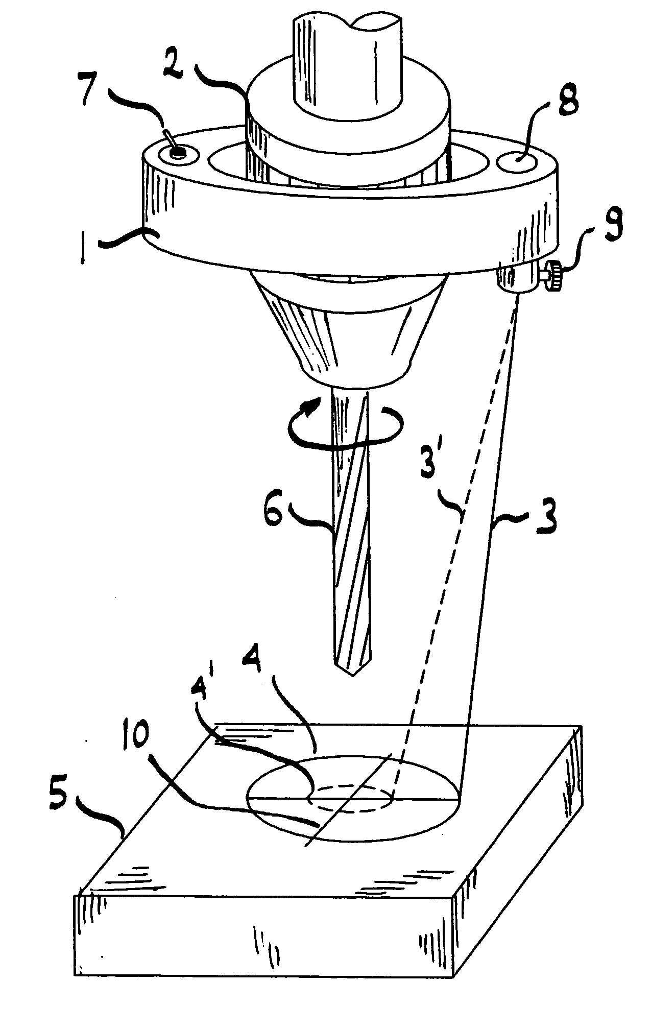
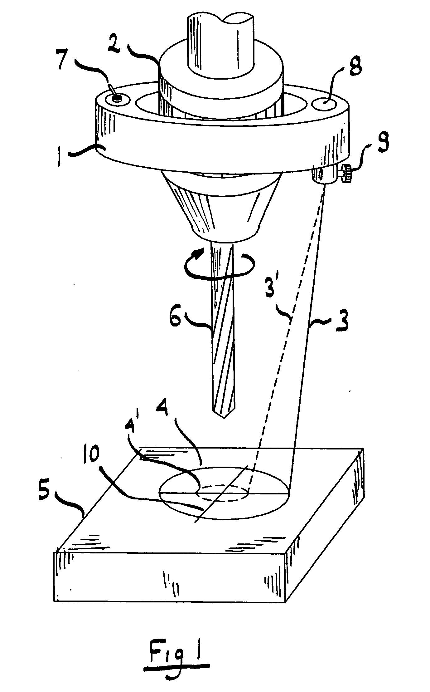
[0010] In FIG. 1 the centerline of cutting tool 6 held in chuck 2 has to be aligned with a feature 10 of work piece 5. Chuck 2 is mounted on a rotating spindle of a machine tool (not shown) such as a milling machine or drill press. Work piece 5 is normally clamped to the table of the machine tool and can be moved in two perpendicular directions. Since machine tools are well known, no details of the machine tool are shown. It is also clear that cutting tool 6 can be one of many different tools such as drill, reamer, tap, boring tool, end mill etc. It is also clear that chuck 2 can also be a collet, a boring head or any other means of holding a cutting tool to a rotating spindle.

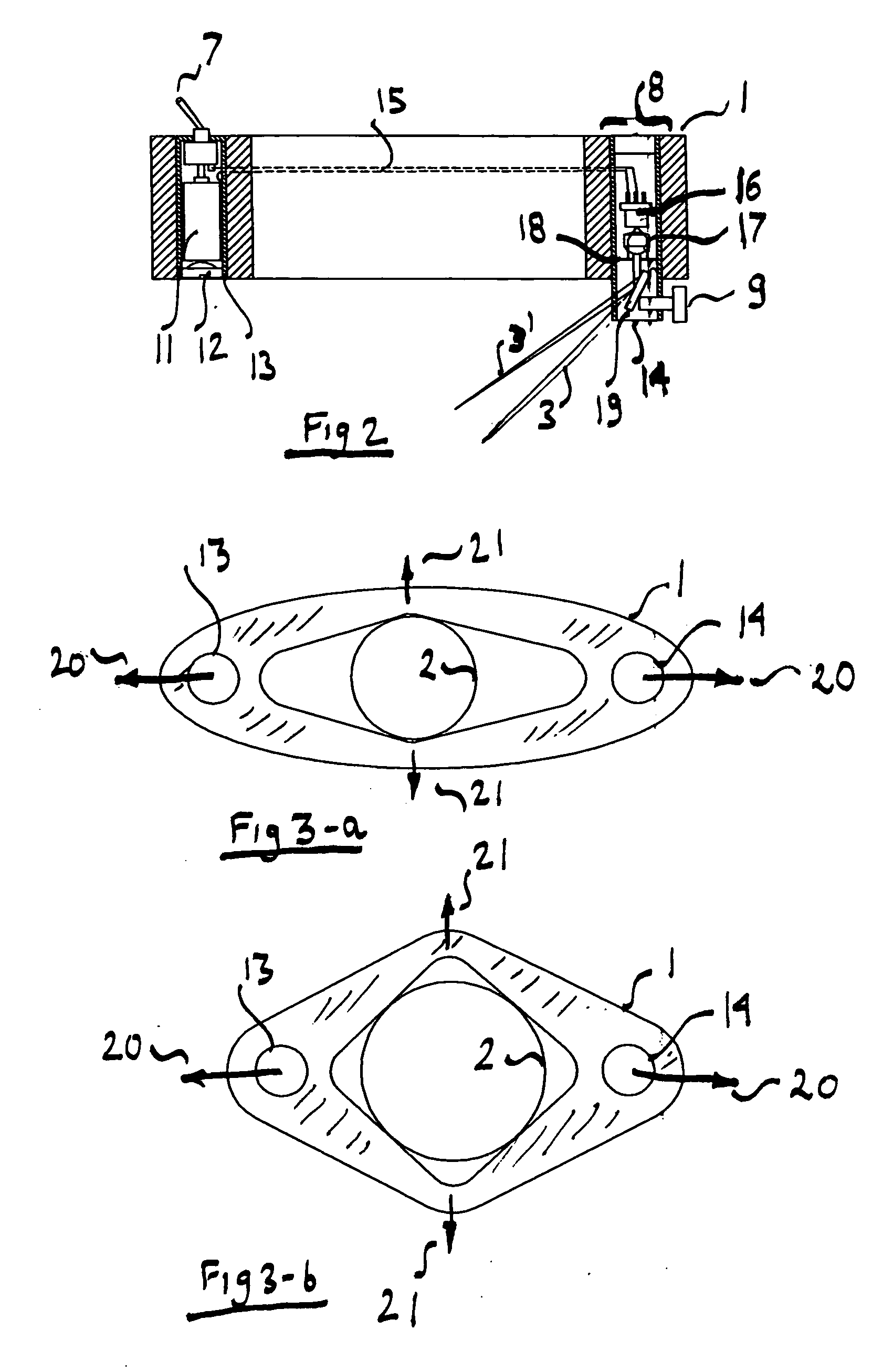
[0011] Alignment jig 1 is temporarily clamped on chuck 2. Switch 7 turns on a laser diode beam projector 8. Beam position can be adjusted by screw 9. As beam is adjusted from position 3 to 3′ the circle formed when spindle is rotated will change from 4 to 4′. The exact size or position of circle are of no imp...


PUM

PropertyMeasurementUnit
Diameteraaaaaaaaaa
Sizeaaaaaaaaaa
Speedaaaaaaaaaa

Abstract

The invention relies on the visual persistence of the human eye to perceive a circle when a laser spot is rotated rapidly. A diode laser spot projector is temporarily attached to the spindle of a machine tool and projects a sharp spot on the work piece. As the spindle rotates, an image of a circle is formed which is perfectly centered with the axis of rotation of the spindle. The work piece is moved until the projected circle lines up with the desired location for machining. The size of the projected circle can be changed by adjusting the position of the laser beam or by changing the distance between the spindle and work piece. The jig can accommodate a wide range of chuck and collet diameters.

Description

FIELD OF THE INVENTION [0001] The invention relates to machine tools, in particular using a laser for aligning of a tool bit to a work piece. BACKGROUND OF THE INVENTION [0002] Optical alignment methods are well known, including their use in machine tools. The invention of the laser, and in particular laser diodes, allowed a high brightness source to be used for improved visual alignment. Prior art use of lasers in machine tools, and in particular in drilling and milling machines, is based on projecting a laser spots or beams which are aligned with the center of rotation of the machine tool spindle. Since the centerline of the cut made by the tool bit (e.g. drill or milling cutter) coincides with the centerline of spindle rotation, aligning the spindle axis of rotation with the desired centerline of the feature to be cut will result in a correctly placed hole or cut. [0003] Prior art methods require an accurate alignment of the laser to the spindle axis of rotation, or require compl...

Claims


Application Information

Patent Timeline
IPC IPC(8): G01B11/00
CPCB23Q17/2233G01B11/27Y10T408/21Y10T409/303752Y10T408/03
Inventor GELBART, DANIEL
Owner GELBART DANIEL
Why Eureka
Try Eureka