
Architectural fabric

a technology of architectural fabric and tensioning, applied in the field of architectural fabric, can solve the problems of reducing the lifetime of architectural fabric, steel cables tend to rub against the membrane, and the attachment is not easy to be easily attached to the membrane, and achieves the effect of not excessively stretching and being easy to apply

Inactive Publication Date: 2007-02-08
NV BEKAERT SA
View PDF16 Cites 5 Cited by
  • Summary
  • Abstract
  • Description
  • Claims
  • Application Information

AI Technical Summary

Benefits of technology

The invention is an architectural fabric that solves issues with previous designs. It is stronger, flexible, and can withstand weather influences over longer periods of time. The fabric is made up of a membrane and a grid of tension members. The tension members are embedded in a polymer matrix and are sealed from climatic circumstances. The strength members can be made out of steel cords. Overall, the fabric is easier to apply, more durable, and better suited for various applications.

Problems solved by technology

However, due to their round shape they are not easily attachable to the membrane (Req. 5).
Due to the wind, the steel cables tend to rub against the membrane.
Over time the cord can even cut through the membrane, thus decreasing the lifetime of the architectural fabric.
Also steel cables tend to corrode contrary to Req. 5. Especially in a damp and wet atmosphere—possibly enhanced by the enclosure of the sleeve—even galvanised cords are ultimately prone to rusting.

Method used


Image

  • Architectural fabric
  • Architectural fabric
  • Architectural fabric

Examples


Embodiment Construction

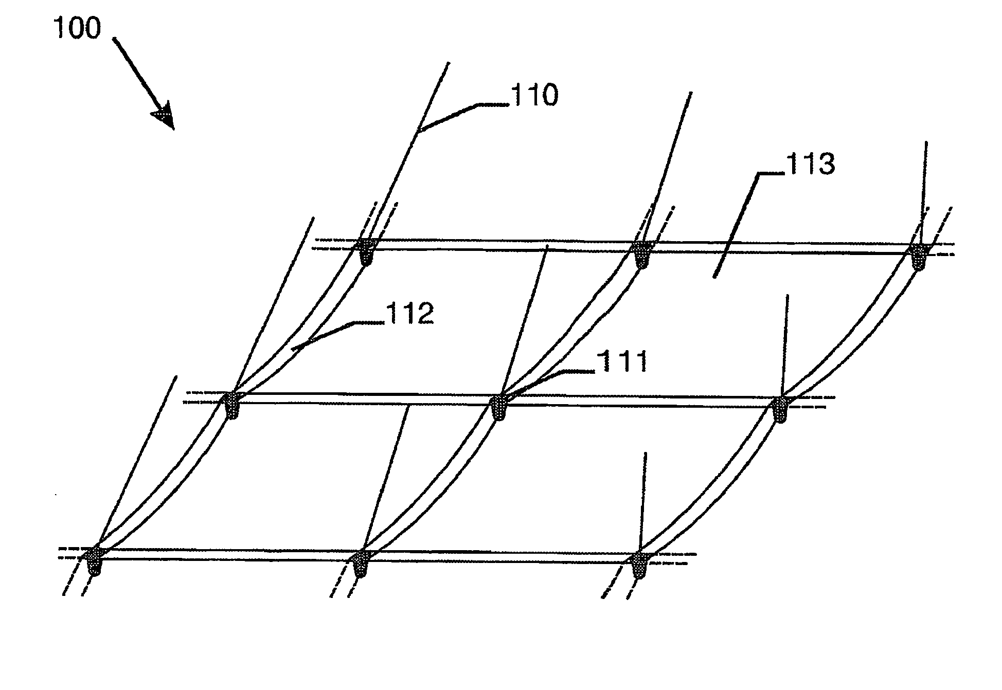
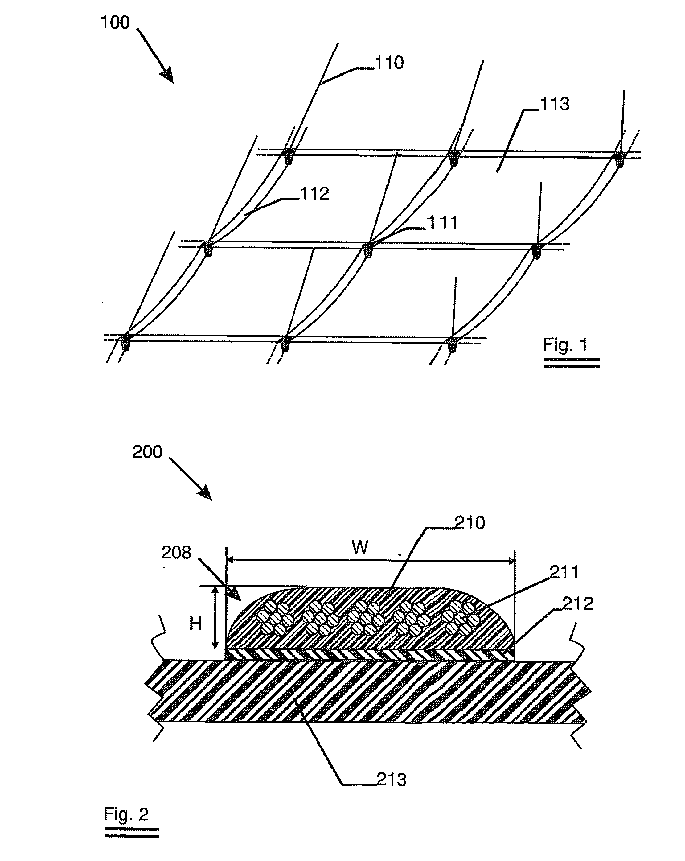
[0038]FIG. 1 shows an architectural fabric of the suspended type according the invention. The architectural fabric 100 comprising one membrane 113 and a tension member 112 is shown. At the crossing points the tension members are turnably attached to one another by means of connector 111.

[0039]FIG. 2 shows a cross section of an architectural fabric 200 according the invention with a single membrane 213. The tension member 208 comprises steel cords 211 embedded in a polymer matrix 210. As the height H is much less than half of the width W, the tension member thus forms a strip. A double-sided self-adhesive tape 212 is used to intimately connect the strip to the membrane.

[0040] Such a strip has been produced by means of extrusion and had the following properties:

TABLE 1Number of cords10Cord type and diameter7 × 19 / 3.2Coating typeHot dip galvanisedWidth × Height of strip38 mm × 5 mmMatrixPolyurethaneDesmopan 8603Breaking load of strip100 406 N(repeated measurement)103 171 NMass per ...


PUM

PropertyMeasurementUnit
tensile strengthaaaaaaaaaa

Abstract

An architectural fabric is claimed where the tension members are strips. These strips comprise a tension member and a polymer matrix. The matrix is preferably of the thermoplastic type and is preferably chemically attached to the polymer used for the membrane. However, mechanical fastening of the strip to the membrane or a combination of chemical and mechanical fastening is not excluded. The advantages are that such a strip is better weather resistant, offers better strength to weight ratios and gives a larger contact surface to the membrane.

Description

FIELD OF THE INVENTION [0001] The invention relates to architectural fabrics as used to protect and isolate large building infrastructures from climatic conditions. More specifically it relates to tensioned fabric structures such as air-supported structures, suspended structures and tensegrity structures. BACKGROUND OF THE INVENTION [0002] Tensioned architectural fabric structures—be it air supported, suspended structures or tensegrity structures—are known as building elements notably for roof structures. These structures, mainly used to cover large surfaces without needing many intermediate support columns—such as sport stadiums—comprise sheet-like flexible materials that are attached to a grid of elongated tension members. The sheet-like flexible material is mostly in the form of a reinforced foil or canvas, called a membrane in what follows. The common feature of these structures is that only tensile forces occur on the membrane thus holding it tight at all times. These tensile f...

Claims


Application Information

Patent Timeline
Patent Type & Authority Applications(United States)
IPC IPC(8): B32B27/12D03D15/00B32B5/22B32B27/04E04D5/12E04H15/18E04H15/20
CPCE04D5/12E04H15/20E04H15/18Y10T442/109Y10T442/172Y10T442/2139Y10T442/164
Inventor HERMANS, PATRICKOFF, ROBERT
Owner NV BEKAERT SA
Learn More