Frequency translating repeater with low cost high performance local oscillator architecture

a local oscillator and frequency translation technology, applied in the field of wireless networks, can solve the problems of signal anomalies, transmission signal down-conversion into the receive band, jamming effect, etc., and achieve 80 db of isolation between two different lo circuits on the same substra

Inactive Publication Date: 2007-02-08
QUALCOMM INC
View PDF99 Cites 26 Cited by
  • Summary
  • Abstract
  • Description
  • Claims
  • Application Information

AI Technical Summary

Problems solved by technology

In particular, signal input stages and even auxiliary circuit input stages, such as LO stages, are susceptible to any in-band signal energy thus signal energy from other than the intended input signal can cause signal anomalies such as interference or “jamming” as will be appreciated.
Further, if the LO used for frequency up-conversion in the transmit path is allowed to leak into the receiver frequency down-converter, the transmitted signal will be down-converted into the receive band and will also have a jamming effect.
While the signal energy coupled through the substrate is typically at a much lower level than coupling through tank circuits as described, achieving 80 dB of isolation between two different LO circuits on the same substrate is still difficult.
Broad-band phase noise is another form of signal anomaly leading to receiver desensitization.
The resulting leakage noise of −165 dBm / Hz as described above results in about 1-1.5 dB of desensitization.
Still another problem associated with any switched LO architecture is pulling.
Pulling is related to instability of the LO due to changes in the output impedance presented to them.
LO pulling will cause disruption in the signal being mixed with the LO until the LO settles back on frequency.
In certain instances, for example in 802.11 signal scenarios, because the 802.11(g) signal has a very short preamble typically 8 μs long, even small amounts of pulling can be catastrophic.

Method used


Image

  • Frequency translating repeater with low cost high performance local oscillator architecture
  • Frequency translating repeater with low cost high performance local oscillator architecture
  • Frequency translating repeater with low cost high performance local oscillator architecture

Examples


Embodiment Construction

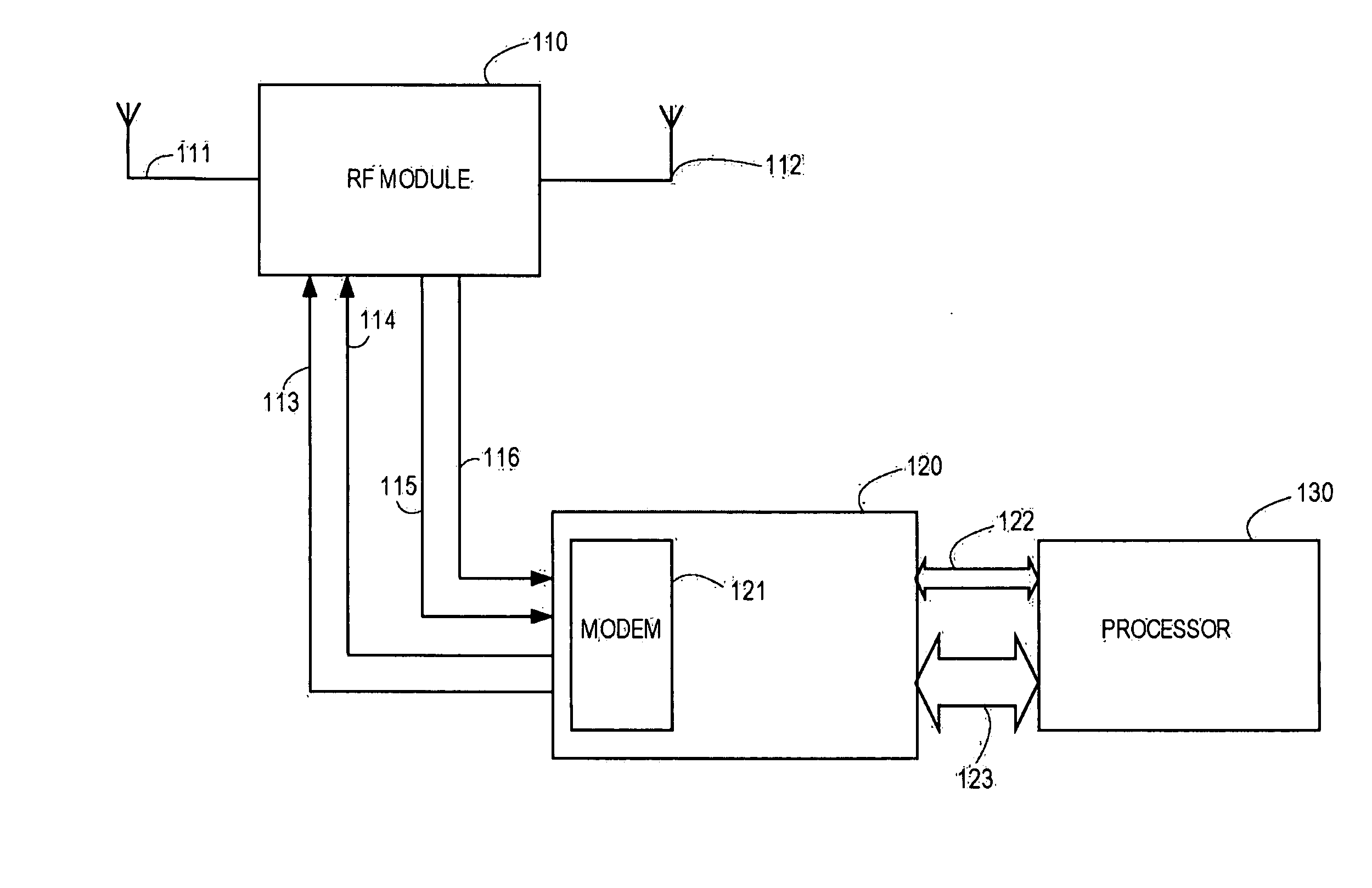
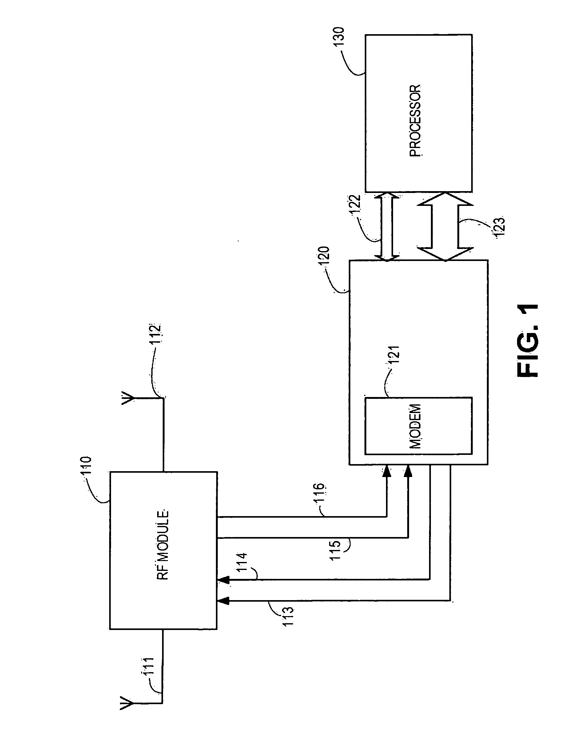
[0014] To better appreciate the basic components of an exemplary repeater, reference is made to FIG. 1. A simplified diagram of the major components of an exemplary frequency translating repeater are shown and include an RF module 110 having a first antennal 111 and a second antenna 112. The RF module 110 is bi-directionally coupled through lines 113, 114, 115, and 116 to a baseband module 120 having a modem 121. It will be appreciated that the modem 121, which can be a beacon modem, or the like, for beacon recovery and processing, requires a sampling clock for demodulation and a frequency carrier for modulation. It should be noted that in accordance with various exemplary embodiments, simultaneous demodulation of both frequency channels is desirable. Accordingly, the number of allowable IF frequencies and the required clock and LO frequencies is limited. Table 1 lists a set of allowable frequencies for an IF and sampling clock in accordance with various embodiments. It will be appr...


PUM


Abstract

A frequency translating repeater (120) for use in a time division duplex (TDD) radio protocol communications system includes local oscillator (LO) circuits (210, 310, and 410) to facilitate repeating by providing isolation, reduced phase noise, reduced pulling, and the like. Tunable LOs (441, 442) can be directly coupled to down-converters (413, 414) and up-converters (426, 427) for increased isolation, reduced phase noise, less stringent frequency accuracy, and a reduced potential for pulling.

Description

CROSS REFERENCE TO RELATED APPLICATIONS [0001] This application is related to and claims priority from pending U.S. Provisional Application No. 60 / 576,290 filed Jun. 3, 2004 and is further related to U.S. patent application Ser. No. 10 / 529,037 filed Mar. 24, 2005 entitled WIRELESS LOCAL AREA NETWORK WITH REPEATER FOR ENHANCING NETWORK COVERAGE (claiming priority from PCT Application PCT / US03 / 28558), and U.S. patent application Ser. No. TBD, filed May 3, 2005 entitled WIRELESS LOCAL AREA NETWORK REPEATER WITH DETECTION (claiming priority from PCT Application PCT / US03 / 35050), the contents of which are incorporated herein by reference.BACKGROUND OF THE INVENTION [0002] The present invention relates generally to wireless networks and, particularly, the present invention relates to a local oscillator (LO) architecture in a frequency translating repeater. In particular, practical considerations must be addressed when implementing such a repeater in a system where many or all the component...

Claims


Application Information

Patent Timeline
Patent Type & Authority Applications(United States)
IPC IPC(8): H04B7/14H04B1/06H04B7/00H04B7/12H04B7/15H04B7/155
CPCH04B7/15528H04B7/12H04B7/15H04B7/00
Inventor GAINEY, KENNETH M.NEGUS, KEVINOTTO, JAMES C.PROCTOR,, JAMES A. JR.
Owner QUALCOMM INC
Why Eureka
Try Eureka