Concealed top track system for sliding doors

a top track and sliding door technology, applied in the field of sliding doors, can solve the problems of long installation time, many such installations do not present an aesthetically pleasing appearance, and the support system should exhibit a long life, and achieve the effect of low friction surfa

Inactive Publication Date: 2007-02-15
RENIN CORP US
View PDF27 Cites 4 Cited by
  • Summary
  • Abstract
  • Description
  • Claims
  • Application Information

AI Technical Summary

Benefits of technology

[0013] Synthetic resin bearing members are seated in the tubular formations to provide a low friction surface and bearing members have a body portion seated in the tubular formation and a collar disposed outwardly thereof which is of larger diameter. The collar is also of larger diameter than the channels of the top track so as to snap fit thereinto.

Problems solved by technology

Moreover, the support system should exhibit long life.
Many such installations require a multiplicity of compounds and fasteners and can require a substantial amount of time for installation.
Moreover, many such installations do not present an aesthetically pleasing appearance since elements of hardware are exposed to a view from within the room.

Method used


Image

  • Concealed top track system for sliding doors
  • Concealed top track system for sliding doors
  • Concealed top track system for sliding doors

Examples


Embodiment Construction

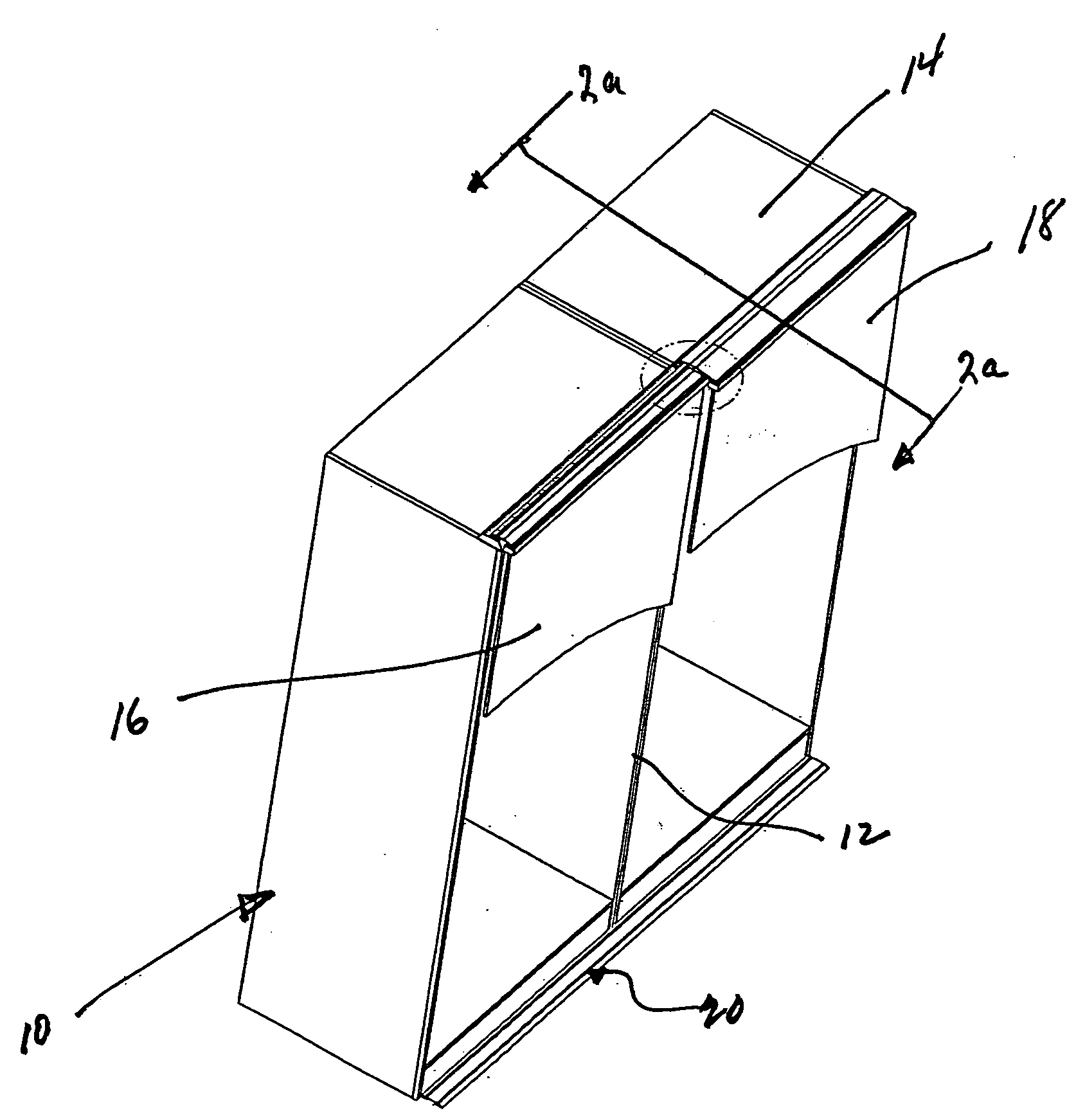
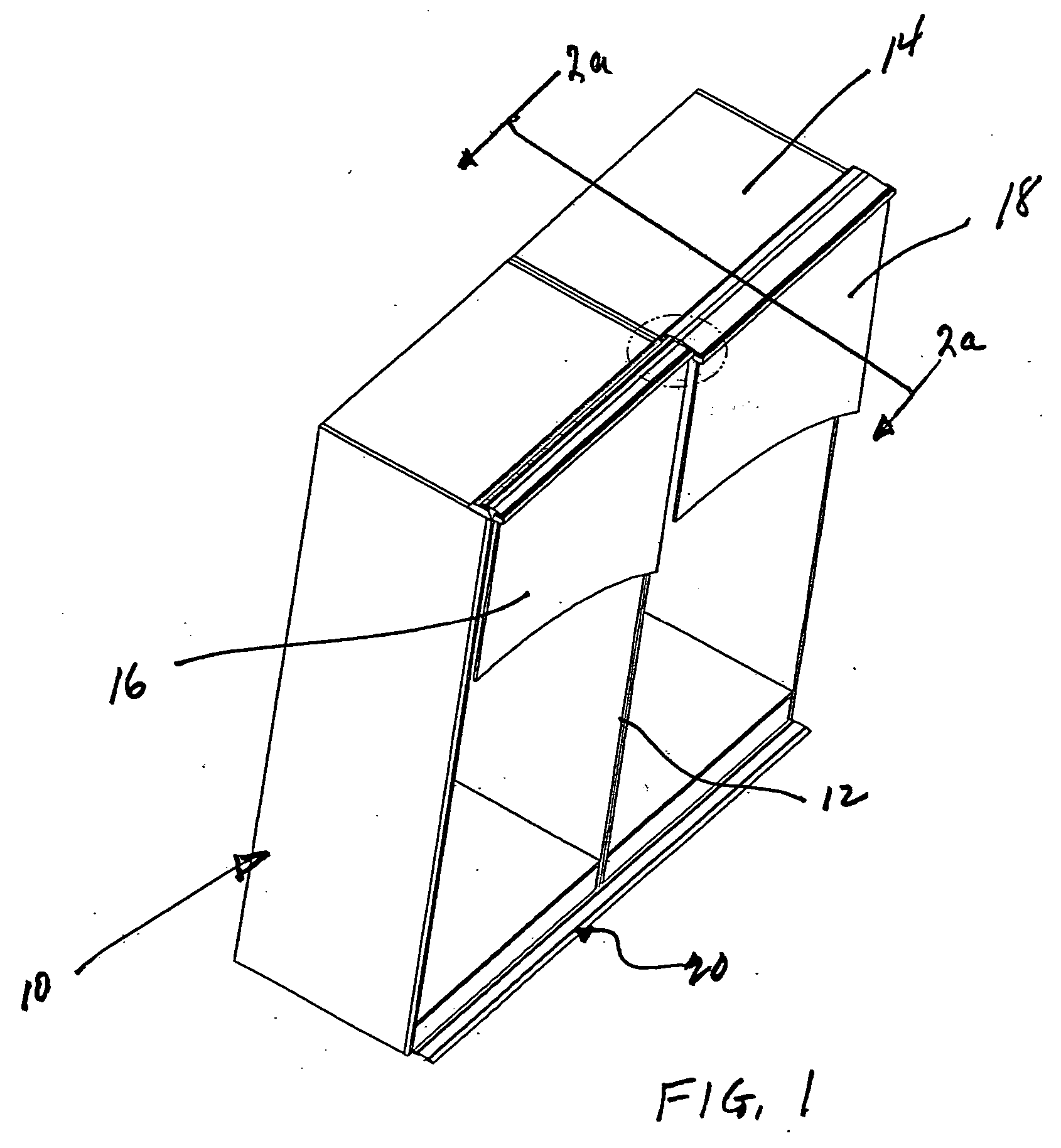
[0032] Turning first to FIG. 1, therein illustrated is a wardrobe with the concealing top track assembly of the present invention. The wardrobe is generally designated by the numeral 10 and has an interior space with a divider 12, and a top wall 14. A pair of sliding doors generally designated by the numerals 16, 18, are dimensioned to close the open face of the wardrobe 10 and are supported for movement on a bottom track assembly generally designated by the numeral 20.

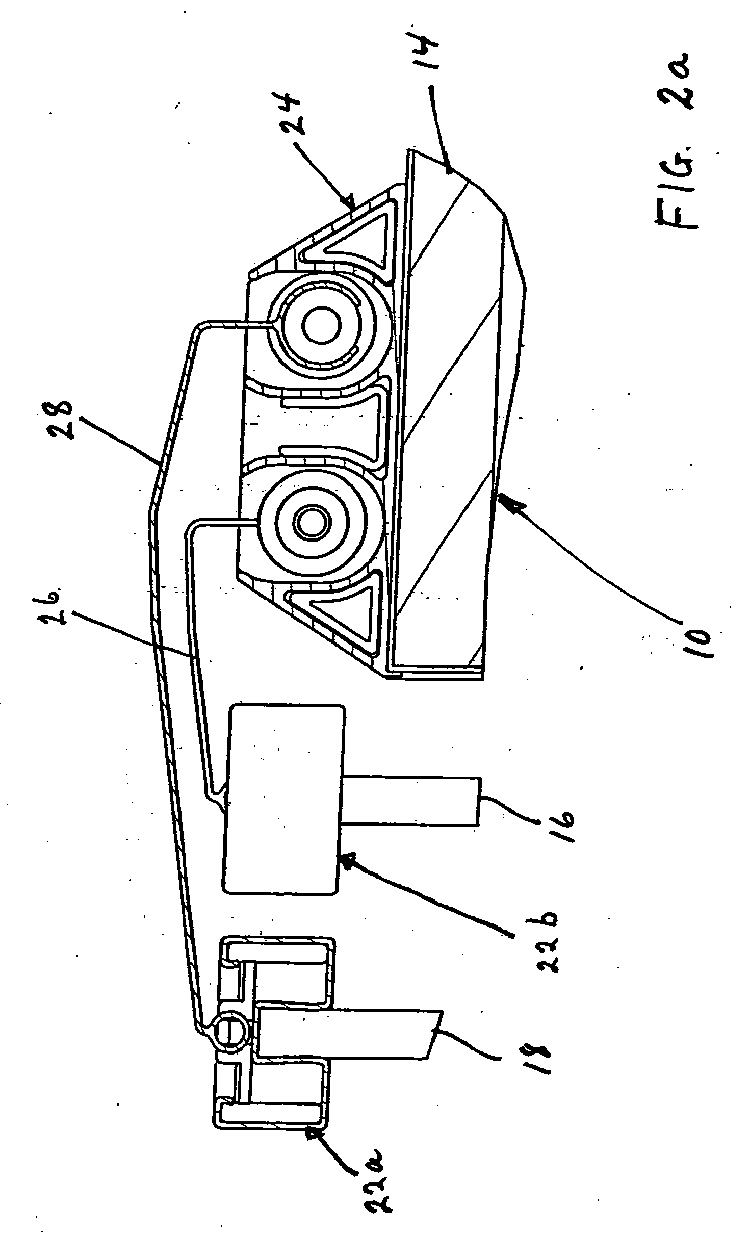
[0033] As seen in FIGS. 2a and 2b, the top track assembly of the present invention includes the top rails generally designated by the numerals 22a and 22b of the doors 16, 18, the top track generally designated by the numeral 24 which is mounted on the top wall 14 of the wardrobe 10 and inner and outer guides generally designated by the numerals 26, 28. The guides 26, 28 are coupled to the top rails 22a and 22b on the doors 16, 18 so that they move as a unit with the associated door and they conceal most of the top t...


PUM


Abstract

A concealing guide track assembly for the top of a pair of sliding doors of a wardrobe having top rails. An elongated top track for mounting on the top wall of the wardrobe has a base wall and spaced channels. First and second elongated guides have a tubular formation along one side edge thereof slidably seated in one of the U-shaped portions of the top track and the other side edge engaged with one of the top rails so as to be slidable therewith. The guides have a bridge portion extending between the side edges, and the second guide bridge portion extends over the bridge portion of the first guide.

Description

BACKGROUND OF THE INVENTION [0001] The present invention relates to sliding doors and more particularly to a door mounting track system which can be mounted at the front of a free standing wardrobe. [0002] Sliding doors are widely employed in closet installations and in free standing wardrobes. In some installations, the weight of the doors is carried by rollers seated in an upper track; in other installations, the weight of the doors is carried by rollers that slide in a floor mounted track. [0003] For a free standing wardrobe in which the doors will be mounted at the front of the wardrobe, it is desirable to employ track components which do not adversely affect the overall appearance of the installation. Moreover, the support system should exhibit long life. Generally, such installations for free standing wardrobes have load bearing wheels or rollers on the sliding doors which run in a track positioned on the floor immediately in front of the wardrobe. The top of each of the doors...

Claims


Application Information

Patent Timeline
Patent Type & Authority Applications(United States)
IPC IPC(8): E05D15/20
CPCE05D15/0626E05Y2900/20E05D15/08E05D15/0652
Inventor JACOBS, KENNETH
Owner RENIN CORP US
Why Eureka
Try Eureka