Lubricant supported electric motor

A technology of electric motor and lubricant, applied in the field of electric motor

Active Publication Date: 2020-05-19
NEAPCO INTPROP HLDG LLC
View PDF4 Cites 0 Cited by
  • Summary
  • Abstract
  • Description
  • Claims
  • Application Information

AI Technical Summary

Problems solved by technology

For electric motors in harsh environments, such as on-wheel motors that are subject to significant mechanical shock, the spindle support issue can be challenging due to the very high levels of shock and vibration that can be encountered at the wheel ends of the vehicle

Method used


Image

  • Lubricant supported electric motor
  • Lubricant supported electric motor
  • Lubricant supported electric motor

Examples


Embodiment Construction

[0021] Example aspects will now be described more fully with reference to the accompanying drawings. In particular, several non-limiting aspects of a vehicle driveline assembly having a wheel support with or without an end gear reduction unit integrated with a wheel end motor are provided such that this disclosure will be comprehensive and will be directed to True and intended ranges are fully conveyed by those skilled in the art. It will be apparent to those skilled in the art that specific details need not be employed, that example aspects may be embodied in many different forms and that neither should be construed to limit the scope of the disclosure. It should also be understood that the present disclosure may be used in connection with other types of vehicle components not adequately described herein.

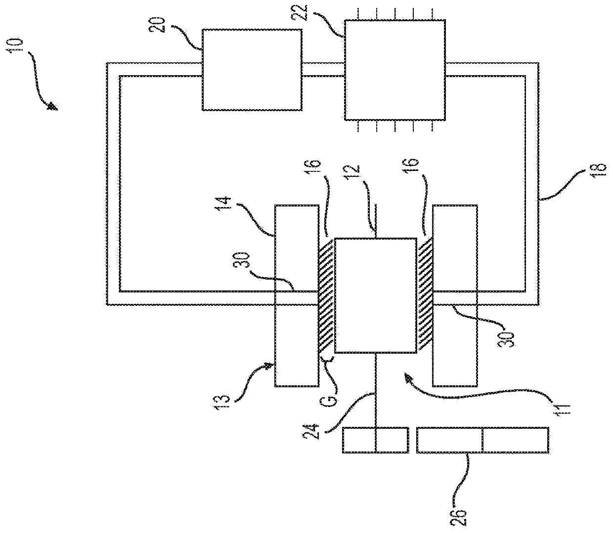
[0022] refer to figure 1 , shows a lubricant supported electric motor 10 having a movable member 11 and a static member 13 . The movable member 11 may be configured as ...


PUM


Abstract

A lubricant supported electric motor includes a static member and a movable member movably disposed within the static member to define a gap therebetween. The static member may be configured as a stator and the movable member may be configured as a rotor. The movable member may also be configured to move relative to the static member. The static member and movable member are configured to exert anelectromagnetic force therebetween and convert electrical energy into mechanical energy and move the movable member. A lubricant is disposed in the gap between the static member and the movable member to support the movable member relative to the static member.

Description

[0001] Cross References to Related Applications [0002] This application claims the benefit of U.S. Provisional Application No. 62 / 563,735, filed September 27, 2017, and U.S. Utility Model Application No. 16 / 144,002, filed September 27, 2018, incorporated by reference Its entire content is incorporated herein. technical field [0003] This disclosure relates to electric motors. More specifically, the present disclosure relates to electric motors having a lubricant support between the rotor and the stator of the electric motor. Background technique [0004] This section of the written disclosure provides background information related to electric motors and is not necessarily prior art to the inventive concepts disclosed and claimed in this application. [0005] Various drivetrains in cars, trucks, and some off-highway applications take power from a central prime mover and distribute it to the wheels using mechanical devices such as transmissions, transaxles, propshafts, a...

Claims


Application Information

Patent Timeline
Patent Type & Authority Applications(China)
IPC IPC(8): H02K7/08H02K41/03H02K7/14
CPCH02K41/031H02K7/088H02K7/14H02K2201/03F16H57/0476F16H57/0441F16H57/0413H02K5/203H02K7/1016H02K7/116H02K1/20F16H57/04H02K9/19
Inventor 唐纳德·伦波斯基杰奎琳·德多
Owner NEAPCO INTPROP HLDG LLC
Why Eureka
Try Eureka