Eureka AIR delivers breakthrough ideas for toughest innovation challenges, trusted by R&D personnel around the world.

Cooling apparatus for internal combustion engine and diagnosis method for the cooling apparatus

a technology for internal combustion engines and cooling apparatuses, which is applied in mechanical apparatus, machines/engines, instruments, etc., can solve the problems of largely deviating from the essentially set value of reference temperature, and erroneously detecting abnormalities of thermostats, so as to improve the detecting accuracy of abnormalities of thermostats

Inactive Publication Date: 2007-02-15
TOYOTA JIDOSHA KK
View PDF13 Cites 19 Cited by
  • Summary
  • Abstract
  • Description
  • Claims
  • Application Information

AI Technical Summary

Benefits of technology

[0008] Accordingly, it is an objective of the present invention to provide a cooling apparatus for an internal combustion engine which can improve a detecting accuracy of an abnormality of a thermostat, and a diagnosis method of the cooling apparatus.

Problems solved by technology

Accordingly, in the cooling apparatus in Japanese Laid-Open Patent Publication No. 2004-316638, in the case that the slope descending state of the vehicle is continued for a comparatively long period before the diagnosis condition is established, there is a possibility that the reference temperature is largely deviated from an essentially set value, and an abnormality of the thermostat is erroneously detected.

Method used


Image

  • Cooling apparatus for internal combustion engine and diagnosis method for the cooling apparatus
  • Cooling apparatus for internal combustion engine and diagnosis method for the cooling apparatus
  • Cooling apparatus for internal combustion engine and diagnosis method for the cooling apparatus

Examples


first embodiment

[0035] A description will be given of a first embodiment in accordance with the present invention with reference to FIGS. 1 to 11.

[0036]

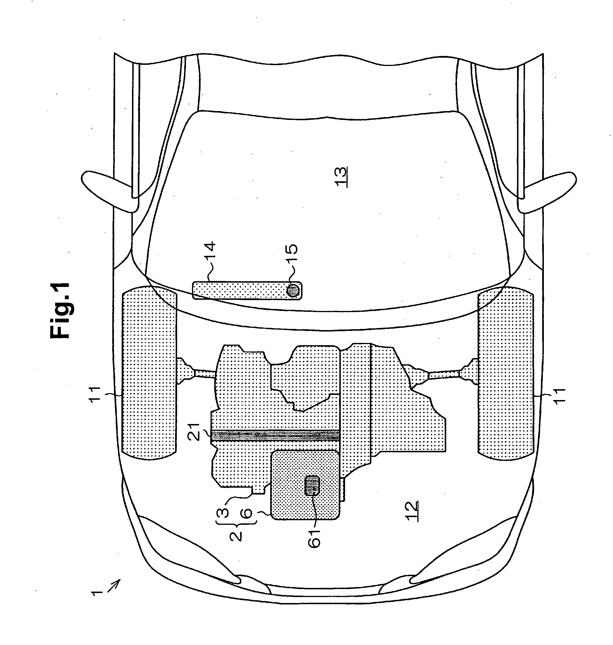
[0037] As shown in FIG. 1, a vehicle 1 travels through rotation of wheels 11 generated by a crankshaft 21 of an engine 2. The engine 2 is mounted within an engine compartment 12 of the vehicle 1, and is provided with an engine main body 3 and a cooling apparatus 6. A cabin 13 of the vehicle 1 is provided with an indicator panel 14 displaying a state of the vehicle 1 and the engine 2.

[0038] The indicator panel 14 is provided with a warning lamp 15 displaying an abnormality of an operating state of a thermostat 61 provided in the cooling apparatus 6. The warning lamp 15 is turned on at a time when the abnormality of the operating state is detected through a diagnosing apparatus mentioned below.

[0039]

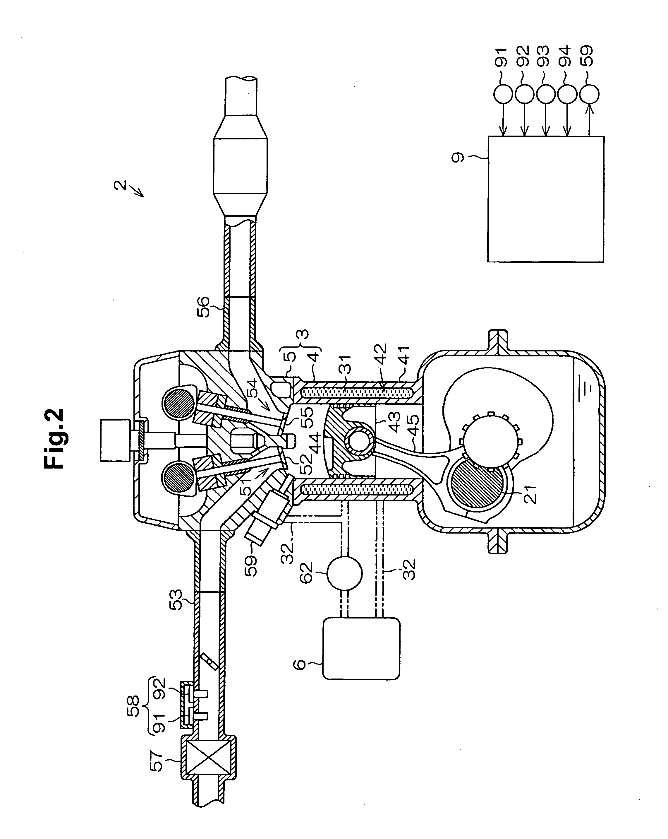
[0040] As shown in FIG. 2, an engine main body 3 is provided with a cylinder block 4 and a cylinder head 5. In the engine main body 3, there is formed ...

second embodiment

[0138] A description will be given of a second embodiment in accordance with the present invention with reference to FIGS. 8, 11 and 12.

[0139] In the first embodiment, the suspension diagnosis of the operating state is selectively executed or suspended on the basis of the descending slope traveling counter value Tcnt. On the contrary, in the present embodiment, the diagnosis of the operating state is selectively executed or suspended on the basis of an integrated time of the descending slope traveling state (a descending slope traveling integrated time TA) from the start of the engine 2 to the diagnosis timing.

[0140]

[0141] In the operating state diagnosing process in accordance with the present embodiment, a process changed from the first embodiment is shown below.

[0142] A simulated water temperature updating process in FIG. 8 is changed in the following point. First, when the traveling state corresponds to the general traveling state in step S120, the simulated water temperature...

third embodiment

[0157] A description will be given of a third embodiment in accordance with the present invention with reference to FIGS. 8, 11 and 13.

[0158] In the first embodiment, the diagnosis of the operating state is selectively executed or suspended on the basis of the descending slope traveling counter value Tcnt. On the contrary, in the present embodiment, the diagnosis of the operating state is selectively executed or suspended on the basis of an integrated time of the descending slope traveling state (a descending slope traveling integrated time TA) from the start of the engine 2 to the diagnosis timing, and an integrated time of the general traveling state (a general traveling integrated time TB).

[0159]

[0160] In the operating state diagnosing process in accordance with the present embodiment, processes changed from and added to the first embodiment are shown below.

[0161] A simulated water temperature updating process in FIG. 8 is changed in the following point. First, in step S122, t...


PUM


Abstract

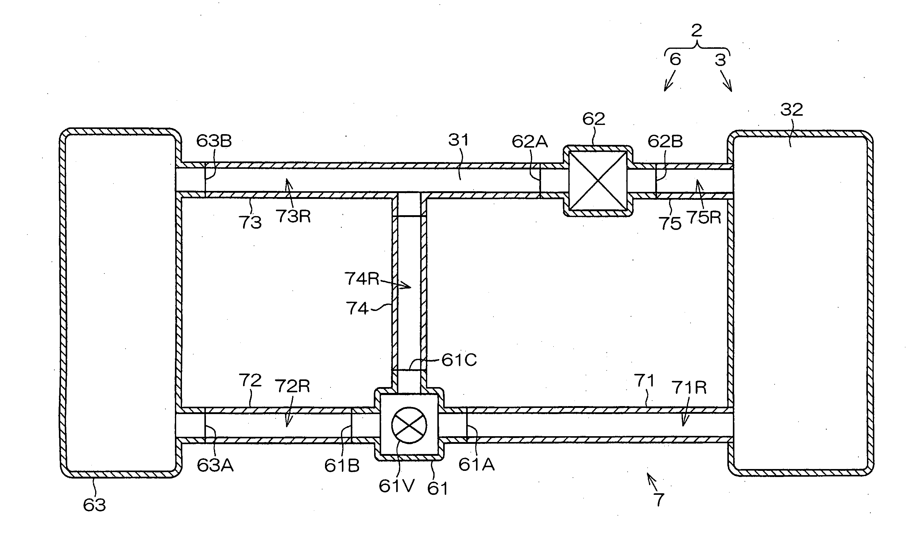
A cooling apparatus for an engine is provided with a thermostat operating in such a manner as to control a supply of a coolant to a radiator. An electronic control apparatus estimates a reference temperature corresponding to a temperature of the coolant on the basis of at least a vehicle speed, and diagnoses an operating state of the thermostat on the basis of a comparison between a detected value of the coolant temperature and the reference temperature. The electronic control apparatus inhibits the diagnosis of the operating state of the thermostat in the case that any one of the following conditions i) to iii) is satisfied. i) a rate of a descending slope traveling time of a vehicle with respect to a time until the diagnosis condition is established from the start of the internal combustion engine is greater than or equal to a determination value; ii) a rate of the descending slope traveling time with respect to a general traveling time is greater than or equal to a determination value; and iii) a rate of a time of a specific state (a state in which a speed of the vehicle is greater than or equal to a reference vehicle speed and a load of the internal combustion engine is less than a reference load) with respect to the time until the diagnosis condition is established from the start of the internal combustion engine is greater than or equal to a determination value.

Description

BACKGROUND OF THE INVENTION [0001] The present invention relates to a cooling apparatus for an internal combustion engine for executing a diagnosis of an operating state of a thermostat and a diagnosis method for the cooling apparatus [0002] In the internal combustion engine, there can be generated a phenomenon (stuck-open valve) that a valve within the thermostat is not operated in an open state. In the state in which the stuck-open valve is generated, since coolant is always circulated via a radiator, a temperature of the coolant is hard to be increased in comparison with a normal state of the thermostat. [0003] Accordingly, in a conventional cooling apparatus including a cooling apparatus described in Japanese Laid-Open Patent Publication No. 2000-220456, the configurationd is made such that an abnormality of the thermostat is detected such as the following items (A) and (B) while paying attention to a difference of a temperature transition of the coolant between a normal state a...

Claims


Application Information

Patent Timeline
IPC IPC(8): F01P7/14F01P5/14
CPCF01P7/167F01P11/14F01P2031/00F01P2023/00F01P2023/08F01P11/16
Inventor MIYAHARA, HIDEKIITO, TOKIJI
Owner TOYOTA JIDOSHA KK
Why Eureka
Eureka Blog
Learn More