Combustion chamber control for combustion-powered fastener-driving tool
Active Publication Date: 2007-02-15
ILLINOIS TOOL WORKS INC
View PDF6 Cites 19 Cited by
Summary
Abstract
Description
Claims
Application Information
AI Technical Summary
This helps you quickly interpret patents by identifying the three key elements:
Problems solved by technology
Method used
Benefits of technology
[0014] The above-listed needs are met or exceeded by the present combustion-powered fastener-driving tool which overcomes the limitations of the current technology. Among other things, the present
Problems solved by technology
This causes the vacuum to be lost and piston travel will stop before reaching the top of the cylinder.
It is disadvantageous to maintain the chamber closed longer than the minimum time to return the piston, as cooling and purging of the tool is prevented.
The main deficiency of this approach is
Method used
Image
Click on the blue label to locate the original text in one second.
Reading with bidirectional positioning of images and text.
Examples
Embodiment Construction
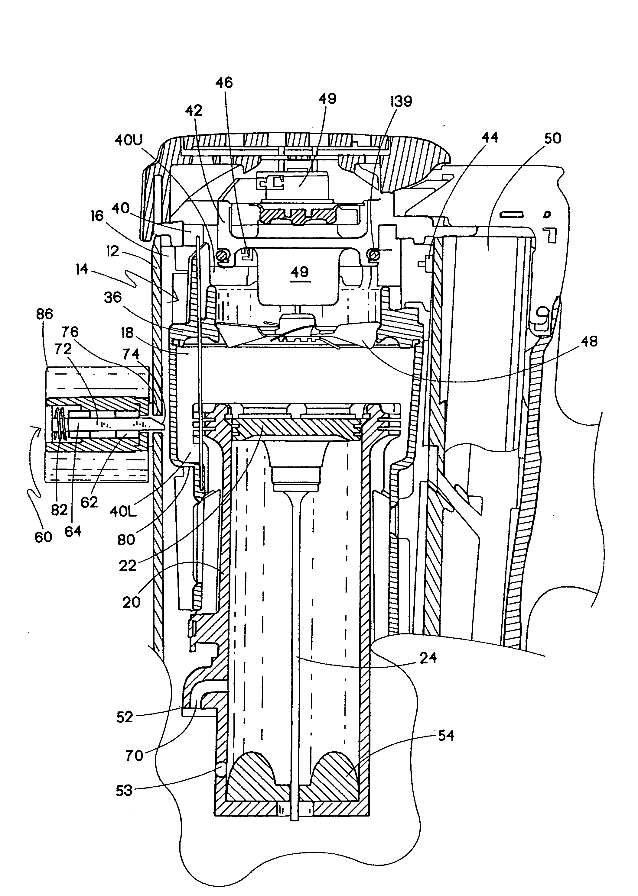
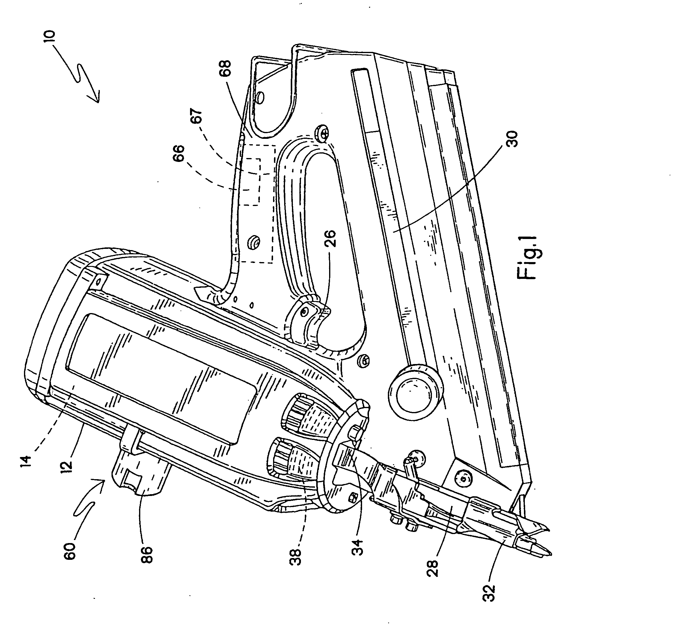
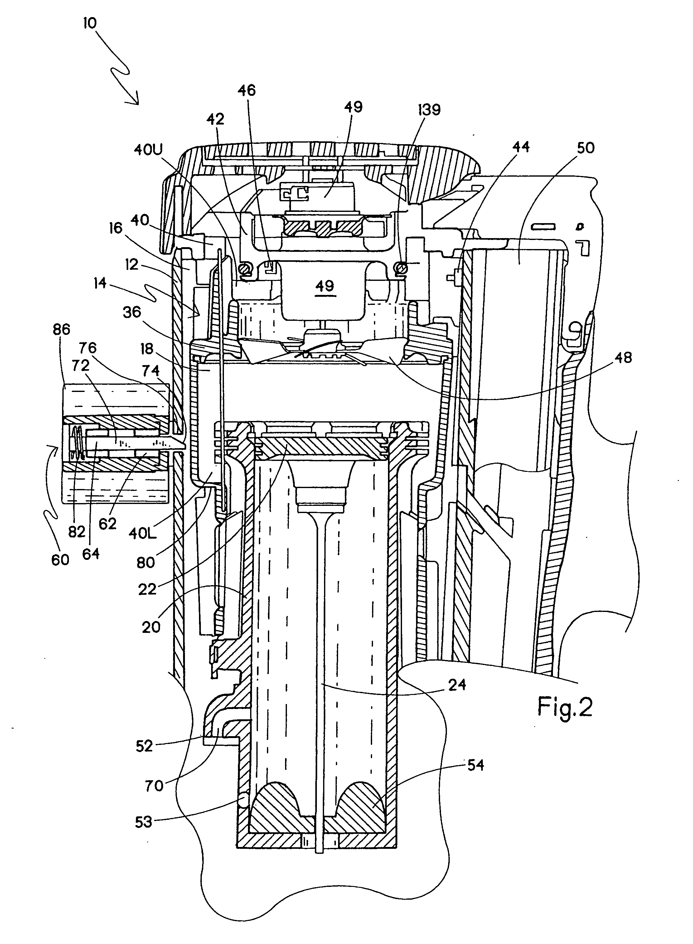
[0030] Referring now to FIGS. 1-3, a combustion-powered fastener-driving tool incorporating the present invention is generally designated 10 and preferably is of the general type described in detail in the patents listed above and incorporated by reference in the present application. A housing 12 of the tool 10 encloses a self-contained internal power source 14 (FIG. 2) within a housing main chamber 16. As in conventional combustion tools, the power source 14 is powered by internal combustion and includes a combustion chamber 18 that communicates with a cylinder 20. A piston 22 reciprocally disposed within the cylinder 20 is connected to the upper end of a driver blade 24. As shown in FIG. 2, an upper limit of the reciprocal travel of the piston 22 is referred to as a pre-firing position, which occurs just prior to firing, or the ignition of the combustion gases which initiates the downward driving of the driver blade 24 to impact a fastener (not shown) to drive it into a workpiece....
PUM
Abstract
A combustion-powered fastener-driving tool includes a combustion-powered power source, a valve sleeve reciprocable relative to the power source between a rest position and a firing position, and a lockout device in operational proximity to the valve sleeve and configured for automatically preventing the reciprocation of the valve sleeve from the firing position until a piston in the power source returns to a pre-firing position.
Description
RELATED APPLICATION [0001] This application claims priority under 35 USC §120 from U.S. Ser. No. 60 / 543,053, filed Feb. 9, 2004 and also from U.S. Ser. No. 11 / 028,432, filed Jan. 3, 2005.BACKGROUND [0002] The present invention relates generally to fastener-driving tools used to drive fasteners into workpieces, and specifically to combustion-powered fastener-driving tools, also referred to as combustion tools. [0003] Combustion-powered tools are known in the art. Exemplary tools are manufactured by Illinois Tool Works, Inc. of Glenview, Ill. for use in driving fasteners into workpieces, and are described in commonly assigned patents to Nikolich U.S. Pat. Re. No. 32,452, and U.S. Pat. Nos. 4,522,162; 4,483,473; 4,483,474; 4,403,722; 5,133,329; 5,197,646; 5,263,439 and 6,145,724 all of which are incorporated by reference herein. [0004] Such tools incorporate a generally pistol-shaped tool housing enclosing a small internal combustion engine. The engine is powered by a canister of press...
Claims
Application Information
Patent Timeline
Application Date:The date an application was filed.
Publication Date:The date a patent or application was officially published.
First Publication Date:The earliest publication date of a patent with the same application number.
Issue Date:Publication date of the patent grant document.
PCT Entry Date:The Entry date of PCT National Phase.
Estimated Expiry Date:The statutory expiry date of a patent right according to the Patent Law, and it is the longest term of protection that the patent right can achieve without the termination of the patent right due to other reasons(Term extension factor has been taken into account ).
Invalid Date:Actual expiry date is based on effective date or publication date of legal transaction data of invalid patent.
IPC IPC(8): B25C1/14
CPCB25C1/08
Inventor MOELLER, LARRY M.DOHERTY, JAMES E.FABIN, JOSEPH E.