This helps you quickly interpret patents by identifying the three key elements:
Problems solved by technology
Method used
Benefits of technology
Benefits of technology
[0008]It is an objective to provide a speed change mechanism which overcomes, or at least mitigates, some or all of the limitations of the known speed change mechanisms.
Problems solved by technology
Additionally, environmental issues have significantly promoted the use of electric bicycles and vehicles in recent years.
Method used
Image
Click on the blue label to locate the original text in one second.
Reading with bidirectional positioning of images and text.
Examples
second embodiment
[0076]In the second embodiment, the output shaft of the power input 2a, which is a DC motor, is offset from the axis of rotation of the first, second and third planetary gear sets 11, 12, 13. The motor 2a has a main body casing 21a and is mounted inside the hub shell 3 to a central shaft or axle 4. The motor has an internal rotor and drive is transmitted from the rotor to the first sun gear 111 through a driving gear 22a and a driven gear 23a.
[0077]The driven gear 23a, the first, the second and the third sun gears 111, 121 and 131, and the power output shaft 143 of the sleeve ring 14 are all mounted co-axially for rotation about the central shaft 4. The internal rotor of the motor and the driving gear 22a are coaxially connected and drive the driven gear 23a which is engaged with the driving gear 22a. The driven gear 23a is coaxially connected to the first sun gear 111 of the first planetary gear set 11 to transmit drive from the motor the speed change mechanism to drive the hub sh...
third embodiment
[0081]In the third embodiment, the power input 2b is an exterior-rotor DC motor of a known type. The advantage of using an exterior-rotor DC motor is that the motor can be positioned within the hub shell 3 of a wheel co-axially with the first, second and third planetary gear sets 11, 12, 13 about a central shaft 4 such as an axle.
[0082]FIG. 6 illustrates schematically a fourth embodiment of a speed change mechanism 1a in accordance with the present invention. The mechanism 1a of the fourth embodiment is essentially the same as that of the first embodiment and so only the differences will be described in detail. In all other respects, the fourth embodiment is constructed and operates in the same manner as the first embodiment and the reader should refer to the above description of the first embodiment for details.
fourth embodiment
[0083]In the previous embodiments, drive is input into each of the first and second planetary gear sets 11, 12 through their respective first and second sun gears and is output by their respective first and second ring gears 114, 124 to achieve a speed reduction through each of the first and second planetary gear sets 11, 12. Thus in the previous embodiments, the first and second sun gears 111, 121 can be considered first and second inputs for the first and second planetary gear sets and the first and second ring gears 114, 124 can be considered as first and second outputs. In the fourth embodiment, the inputs and outputs of the first and second planetary gear sets 11, 12 are reversed so that the first and second ring gears 114, 124 become the first and second inputs and the first and second sun gears 111, 121 become the first and second outputs.
[0084]In the fourth embodiment as shown in FIG. 6, the power input 2 is coupled with the first ring gear 114. As the first carrier arm 113 ...
PUM
Abstract
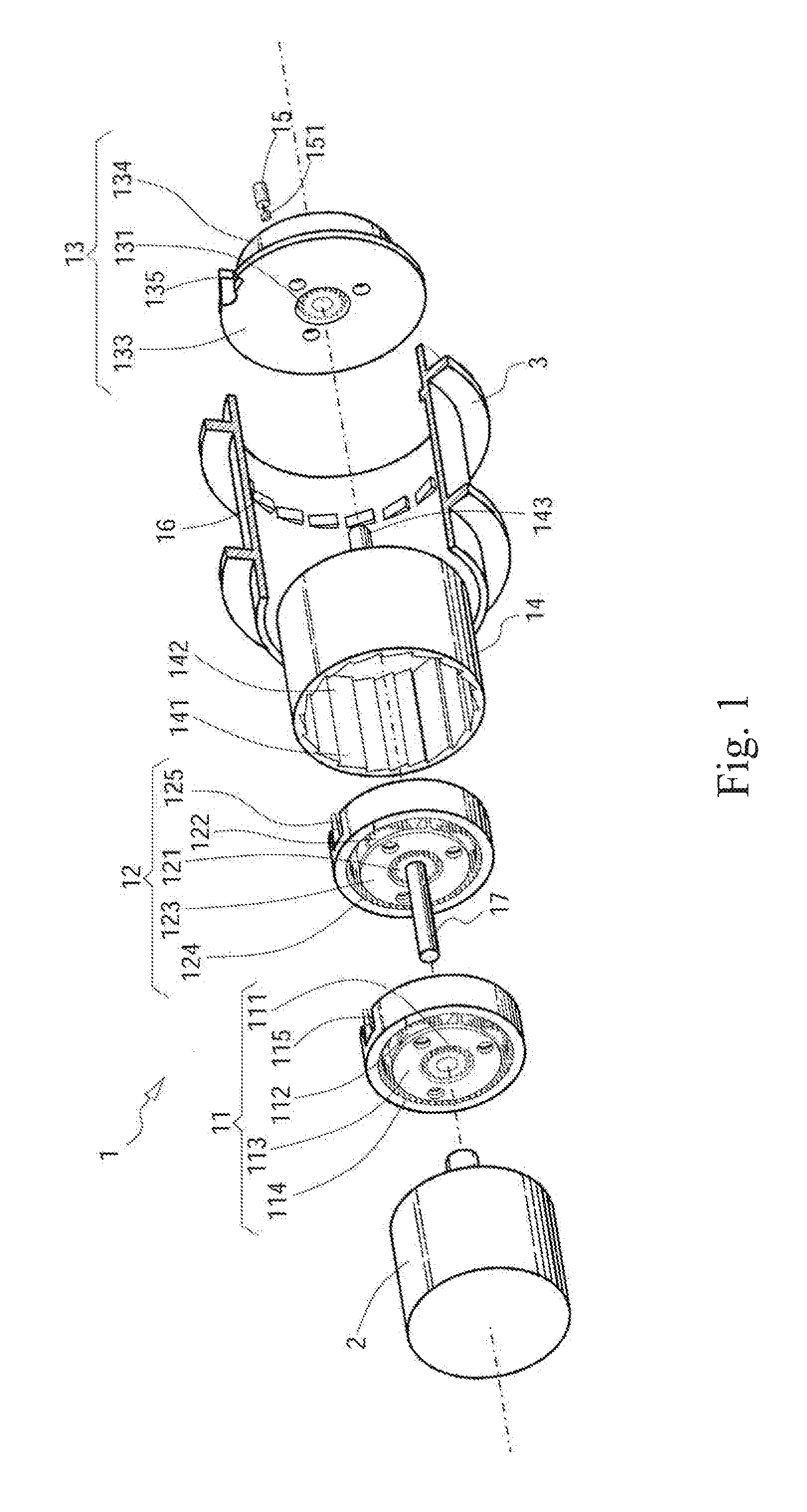
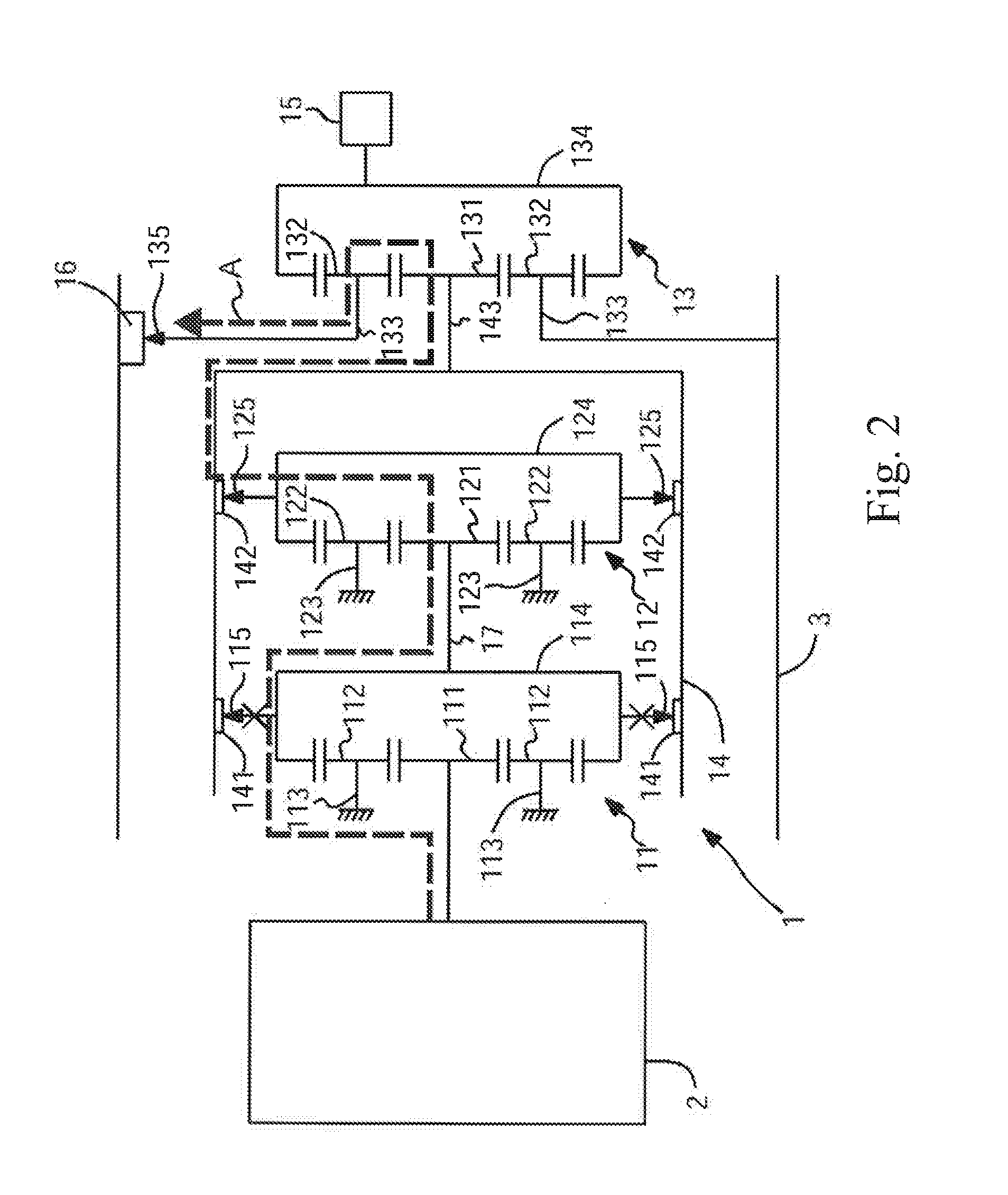
A speed change mechanism 1 includes first and second planetary gear sets 11, 12 enclosed within a sleeve ring 14. A first one-way clutch 141 transmits drive from an output 114 of the first gear set to the sleeve ring and second one-way clutch 142 transmits drive from an output 124 of the second gear set to the sleeve ring, both clutches operating in the same direction. A DC electric motor 2 is coupled to an input 111 of the first gear set to drive its output 114 in the opposite rotary direction to the input. The output 114 of the first gear set is coupled to an input 121 of the second gear set to drive an output 124 of the second gear set in the opposite rotary direction from the output 114 of the first gear set. Drive is transmitted to the sleeve ring 14 either through the first gear set 11 only or through a combination of the first and second gear sets 11, 12 depending on the direction of rotation of the power input to provide two different gear ratios.
Description
FIELD OF THE INVENTION[0001]The present invention relates to a speed change mechanism or transmission, particularly but not exclusively for a motor.BACKGROUND OF THE INVENTION[0002]The transmission is a very important part in speed change electric vehicles or electric hand tools. The whole speed change system typically represents about half of the production cost; therefore research on the speed change mechanism is always an important item for any company in the electric vehicle or the electric hand tool industry. A good transmission can change the rotational speed ratio according to different requirements. For use in an eclectic vehicle such as an electric bike, the transmission can be used to change the speed ratio so as to achieve the objective of an appropriate rotational speed or torque for the rider in different conditions.[0003]Planetary gear sets are commonly used in the transmission of an electric vehicle. A planetary internal transmission uses a planetary gear train as the...
Claims
Application Information
Patent Timeline
Application Date:The date an application was filed.
Publication Date:The date a patent or application was officially published.
First Publication Date:The earliest publication date of a patent with the same application number.
Issue Date:Publication date of the patent grant document.
PCT Entry Date:The Entry date of PCT National Phase.
Estimated Expiry Date:The statutory expiry date of a patent right according to the Patent Law, and it is the longest term of protection that the patent right can achieve without the termination of the patent right due to other reasons(Term extension factor has been taken into account ).
Invalid Date:Actual expiry date is based on effective date or publication date of legal transaction data of invalid patent.

