
Method and apparatus for image enhancement

a technology of image enhancement and apparatus, applied in the field of methods, can solve the problems of not providing conventional cameras do not provide a means for collecting position data, orientation data, or camera parameters, etc., and achieve the effect of increasing accuracy and increasing accuracy

Inactive Publication Date: 2007-02-15
HRL LAB
View PDF99 Cites 181 Cited by
  • Summary
  • Abstract
  • Description
  • Claims
  • Application Information

AI Technical Summary

Benefits of technology

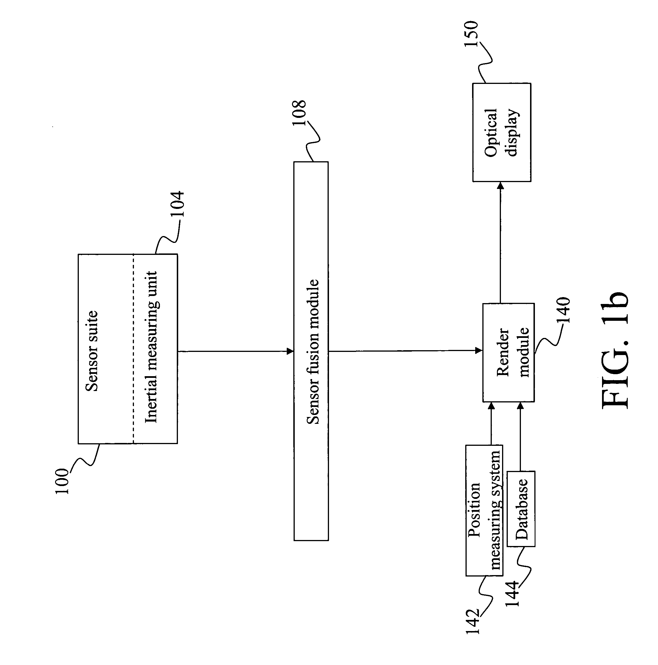
[0020] In yet another aspect, the sensor suite further may further include a compass. The sensor fusion module is connected with a sensor suite compass for accepting a sensor suite compass output from the sensor suite compass; and the sensor fusion module further uses the sensor suite compass output in determining the unified estimate of the user's angular rotation rate and current orientation with increased accuracy.
[0022] In yet another aspect, the sensor suite further includes a sensor suite video camera; and the apparatus further includes a video feature recognition and tracking movement module connected between the sensor suite video camera and the sensor fusion module, wherein the sensor suite video camera provides a sensor suite video camera output, including video images, to the video feature recognition and tracking movement module, and wherein the video feature recognition and tracking movement module provides a video feature recognition and tracking movement module output to the sensor fusion module, which utilizes the video feature recognition and tracking movement module output to provide increased accuracy in determining the unified estimate of the user's angular rotation rate and current orientation..
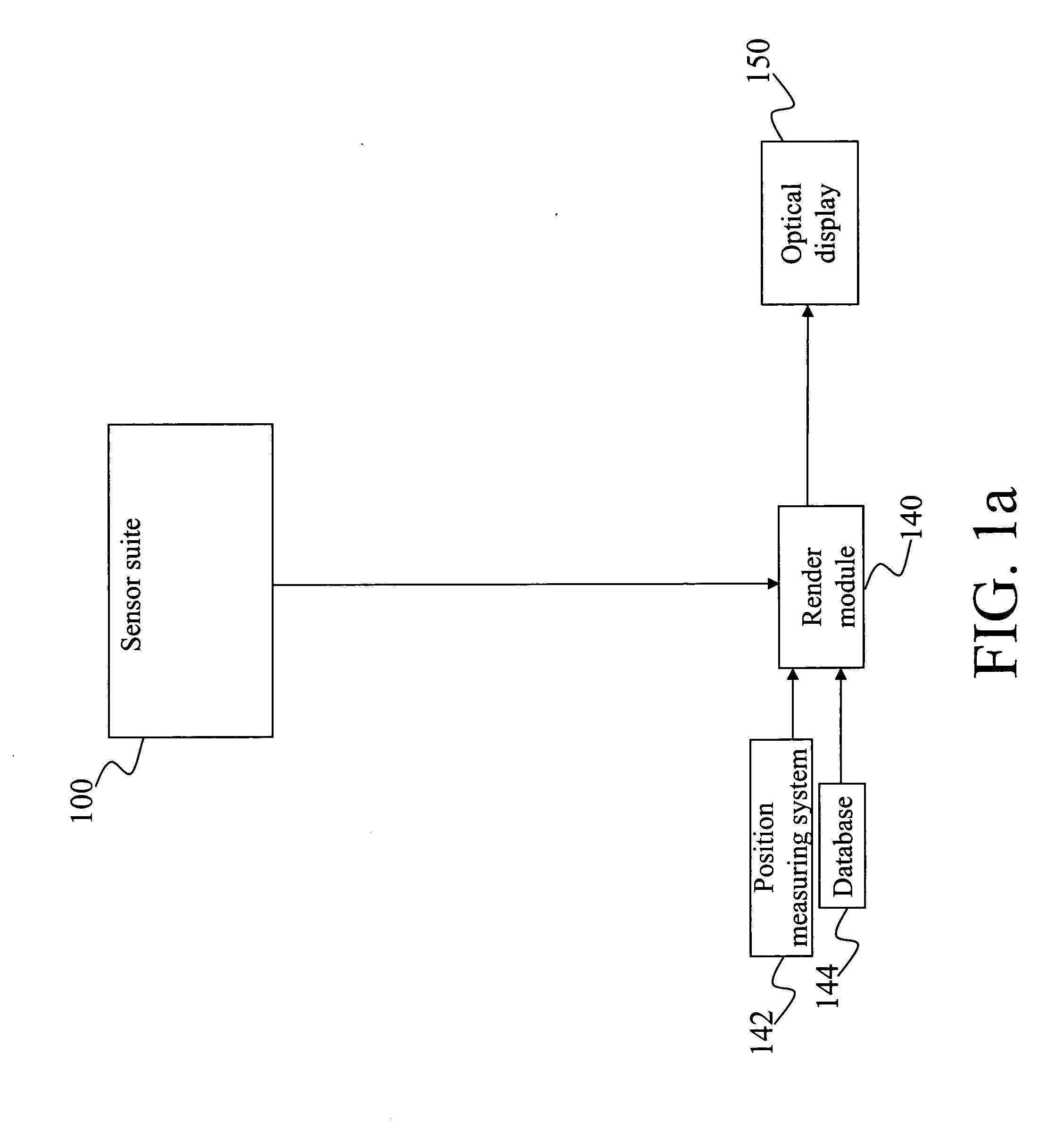
[0024] The present invention in another aspect comprises the method for an optical see-through imaging through an optical display having variable magnification for producing an augmented image from a real scene and a computer generated image. Specifically, the method comprises steps of measuring a user's current orientation by a sensor suite; rendering the computer generated image by combining a sensor suite output connected with a render module, a position estimation output from a position measuring system connected with the render module, and a data output from a database connected with the render module; displaying the combined optical view of the real scene and the computer generated image of an object in the user's current position and orientation for the user to view through the optical display connected with the render module; and repeating the measuring step through the displaying step to provide a continual update of the augmented image.
[0026] An additional aspect, or aspect, of the present invention wherein the step of measuring precisely the user's current orientation by a sensor suite includes measuring the user's current orientation using a compass, and wherein the measurements produce the unified estimate of the user's angular rotation rate and current orientation with increased accuracy.
[0028] In yet another aspect, or aspect, of the present invention, the step of measuring precisely the user's current orientation by a sensor suite further includes measuring the user's orientation using a video camera and a video feature recognition and tracking movement module. The video feature recognition and tracking movement module receives a sensor suite video camera output from a sensor suite video camera and provides the sensor fusion module measurements to enable the sensor fusion module to produce the unified estimate of the user's angular rotation rate and current orientation with increased accuracy.
[0029] In another aspect of the present invention, the step of measuring precisely the user's orientation further includes a template matcher within the video feature recognition and tracking movement module, and provides the sensor fusion module measurements to enable the sensor fusion module to produce the unified estimate of the user's angular rotation rate and current orientation with increased accuracy.

Problems solved by technology

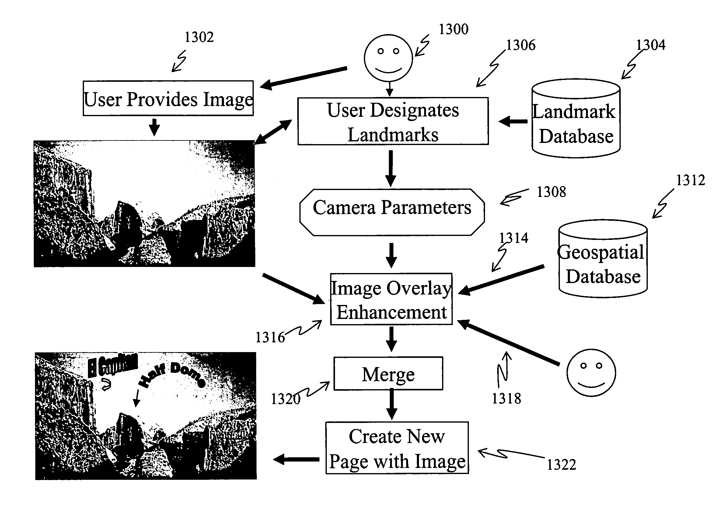
There is currently no automatic, widely accessible means for a static image to be enhanced with content related to the location and subject matter of a scene.
Further, conventional cameras do no not provide a means for collecting position data, orientation data, or camera parameters.
Nor do conventional cameras provide a means by which a small number of landmarks with known position in the image can serve as the basis for additional image augmentation.
Because of the high number of images collected, it is often impractical for the photographer to augment photographs by existing methods.
Further, the photographer will periodically forget where the picture was taken, or will forget other data relative to the circumstances under which the picture was taken.
In these cases, the picture cannot be augmented by the photographer because the photographer does not know where to seek the augmenting information.
Both streams have inherent delays in the tens of milliseconds.
2) Resolution: Video blending limits the resolution of what the user sees, both real and virtual, to the resolution of the display devices, while optical blending does not reduce the resolution of the real world.
On the other hand, an optical approach has the following disadvantages with respect to a video approach: 1) Real and virtual view delays are difficult to match.
The optical approach offers an almost instantaneous view of the real world, but the view of the virtual is delayed.
Currently, optical approaches do not have this additional registration strategy available to them.
Most display devices cannot come close to this level of contrast.
The resolution of video sensing and video display elements is limited, as is the contrast and brightness.
One of the most basic problems limiting AR applications is the registration problem.
The objects in the real and virtual worlds must be properly aligned with respect to each other, or the illusion that the two worlds coexist will be compromised.
The biggest single obstacle to building effective AR systems is the requirement of accurate, long-range sensors and trackers that report the locations of the user and the surrounding objects in the environment.
Few trackers currently meet all the needed specifications, and every technology has weaknesses.
Without accurate registration, AR will not be accepted in many applications.
Registration errors are difficult to adequately control because of the high accuracy requirements and the numerous sources of error.
However, registration and sensing errors have been two of the basic problems in building effective magnified optical AR systems.

Method used


Image

  • Method and apparatus for image enhancement
  • Method and apparatus for image enhancement
  • Method and apparatus for image enhancement

Examples


Embodiment Construction

[0061] The present invention is generally related to image enhancement and augmented reality (“AR”). More specifically, this invention presents a method and an apparatus for static image enhancement and the use of an optical display and sensing technologies to superimpose, in real time, graphical information upon a user's magnified view of the real world.

[0062] The following description, taken in conjunction with the referenced drawings, is presented to enable one of ordinary skill in the art to make and use the invention and to incorporate it in the context of particular applications. Various modifications, as well as a variety of uses in different applications, will be readily apparent to those skilled in the art, and the general principles defined herein may be applied to a wide range of aspects. Thus, the present invention is not intended to be limited to the aspects presented, but is to be accorded the widest scope consistent with the principles and novel features disclosed he...


PUM


Abstract

The present invention is generally related to image enhancement and augmented reality (“AR”). More specifically, this invention presents a method and an apparatus for static image enhancement and the use of an optical display and sensing technologies to superimpose, in real time, graphical information upon a user's magnified view of the real world.

Description

PRIORITY CLAIM [0001] The present application is a continuation-in-part of U.S. patent application Ser. No. 10 / 256,090, now pending, filed Sep. 25, 2002, and titled “Optical See Through Augmented Reality Modified Scale System.”STATEMENT OF GOVERNMENT RIGHTS [0002] This invention is used in conjunction with DARPA ITO contracts #N00019-97-C-2013, “GRIDS”, and #N00019-99-2-1616, “Direct Visualization of the Electronic Battlefield”, and the U.S. Government may have certain rights in this invention.TECHNICAL FIELD [0003] The present invention is generally related to image enhancement and augmented reality (“AR”). More specifically, this invention presents a method and an apparatus for static image enhancement and the use of an optical display and sensing technologies to superimpose, in real time, graphical information upon a user's magnified view of the real world. BACKGROUND [0004] There is currently no automatic, widely accessible means for a static image to be enhanced with content re...

Claims


Application Information

Patent Timeline
Patent Type & Authority Applications(United States)
IPC IPC(8): G09G5/00G03B13/28G06F3/00G06F3/01
CPCG03B13/28G06T19/006G06F3/011G06F3/147H04N13/344H04N13/398
Inventor AZUMA, RONALD T.SARFATY, RON
Owner HRL LAB
Learn More