

Line-dot recorder
- Summary
- Abstract
- Description
- Claims
- Application Information
AI Technical Summary
Benefits of technology
Problems solved by technology
Method used
Image

Examples
second embodiment
[0189] Although in the embodiment the rotary drum 2 is rotated at a higher speed than the standard speed for mass printing, the dot recorder according to this invention may have the drum 2 rotated at a lower speed than the standard speed. Such a line dot recorder will be described below as the second embodiment with dot recording conditions such as N sheets of paper, N multi-pass and N-rotation, paper supply means 3 for continuous printing at regular intervals, paper mounting / holding means 4 and paper delivery means 5. But, since the appearance is the same, it is not shown.
[0190] With this embodiment, since the rotary drum 2 is rotated at a lower speed than the standard speed, the period speed, that is, the ink jetting timing from the nozzles of the nozzle head 1, too, is decreased in accord with it. In this embodiment, too, the nozzle head 1 may be moved by the head moving means 10 by a preset short distance. Or else, the head moving means may be omitted. Instead a plurality of noz...
first embodiment
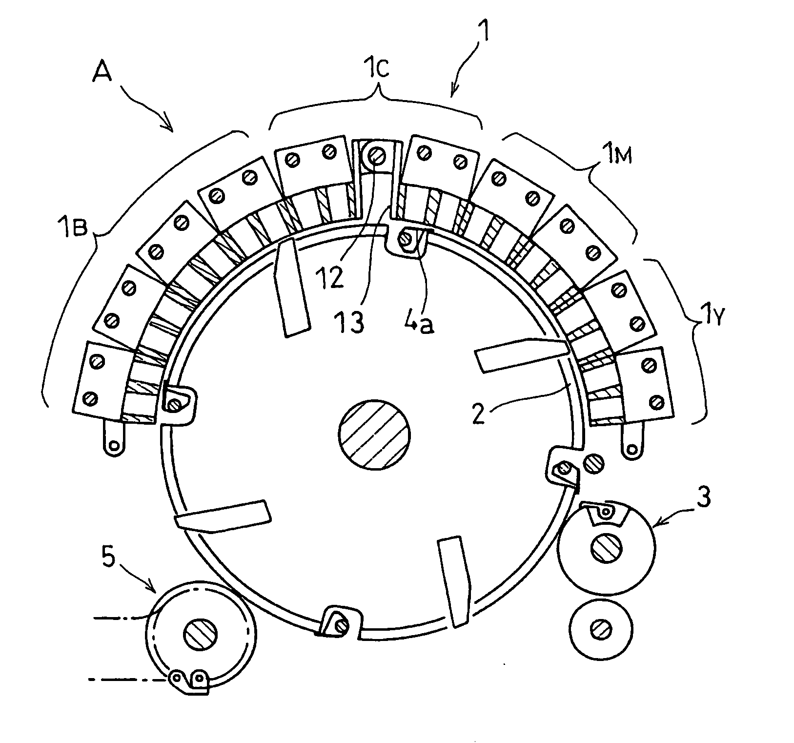
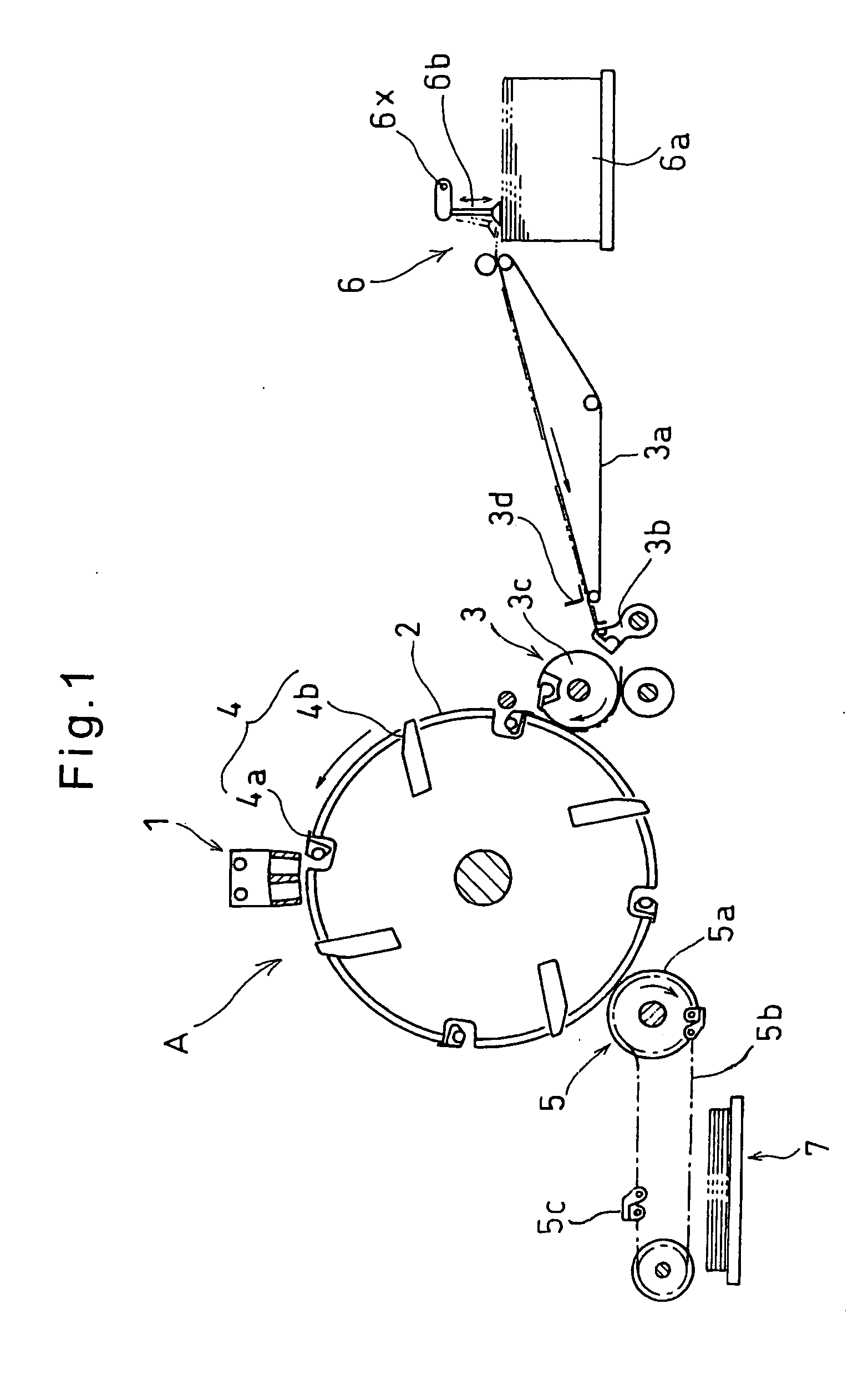
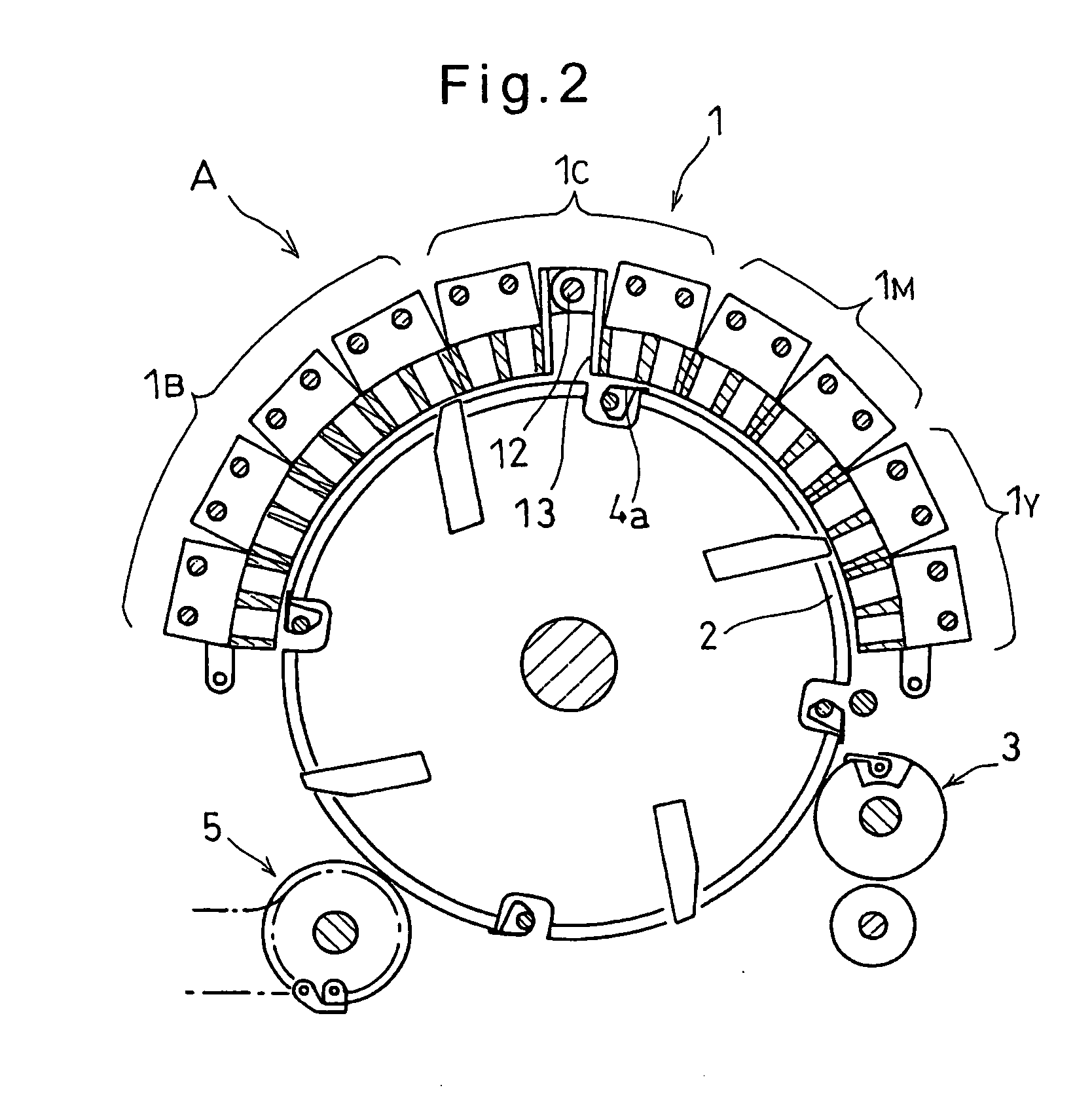
[0204] The paper supply means 3 comprises a paper feed roller 3c and a pivoting gripper 3b. The latter grips one end of the paper P fed one by one by a conveyor 3a from a paper supply tray 6a (storage case in the first embodiment), pivots as shown by arrow in FIG. 14 and feeds it to the paper supply roller 3c.
[0205] The paper supply tray 6a has a suction arm 6b which supplies paper P one by one to the conveyor 3a (by command from the control means). The conveyor 3a is provided with a registering means 3d to align the paper P widthwise and longitudinally. The gripper 3b grips the paper supplied from the conveyor 3a and feeds it to the paper supply roller 3c. The roller 3c grips one end of the paper with a claw 3e, turns as shown by arrow in FIG. 14 and hands the paper to the claw 4a of the drum 2.
[0206] The paper delivery means 5 comprises a paper delivery roller 5a, a chain 5b attached to the roller 5a, and a gripping claw 5c attached to the chain 5b. The gripping claw 5c takes ou...
PUM
 Abstract
Description
Claims
Application Information