Composite image forming system

a technology of composite image and forming system, which is applied in the field of composite image forming system, can solve the problem that it is not easy for users to understand how to set paper and achieve the effect of easy setting on a printing uni

Inactive Publication Date: 2007-02-15
SEIKO EPSON CORP
View PDF7 Cites 32 Cited by
  • Summary
  • Abstract
  • Description
  • Claims
  • Application Information

AI Technical Summary

Benefits of technology

[0004] It is therefore an object of the invention to provide a composite image forming system which prints a mounting, which is used to write a handwritten element on a dimmed photographic image, and a composite image of the handwritten image and the photographic image, wherein paper can be easily set on a printing unit.

Problems solved by technology

However, when the layout of the image is set in favor of decode efficiency, in the event that it is required that the top and bottom of the image match those of the paper, in a case in which a composite image of the handwritten element and the photographic image is printed on, for example, a postcard, it will not be easy for the user to understand how to set the paper on a printing unit in order that the top and bottom of the image match those of the paper.

Method used


Image

  • Composite image forming system
  • Composite image forming system
  • Composite image forming system

Examples


Embodiment Construction

[0046] A mode for carrying out the invention will hereafter be described based on an embodiment.

[0047] 1. Configuration of Composite Image Forming System

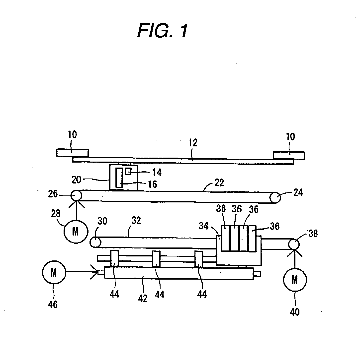
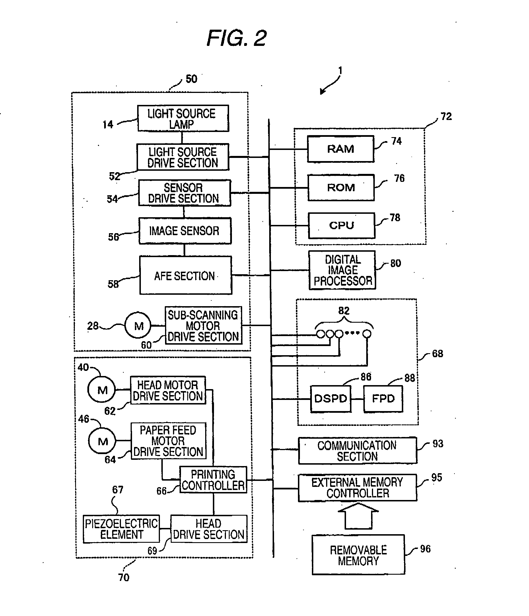
[0048]FIG. 1 is a schematic diagram showing a mechanical structure of a multifunction printer (MFP) 1 serving as an embodiment of a composite image forming system according to the invention. FIG. 2 is a block diagram showing an electrical configuration of the MFP 1. FIG. 3 is a plan view showing an external appearance of the MFP 1. The MFP 1 includes a function of receiving an image from a removable memory 96 and printing it, a function of reading and printing the image, and the like. The composite image forming system may also include a scanner which has an image reading function and a PC which has a function of controlling a printer having a printing function.

[0049] A scanning unit 50 includes a platen glass 12, a platen frame 10 holding the platen glass 12, a CIS (Contact Image Sensor) unit 16, a light source lamp 14, a carria...


PUM


Abstract

A composite image forming system includes a color reduction unit, operable to form a background image which is a raster image by reducing a color gamut of a user image which is a raster image and is stored in a recording medium; an order form printing control unit, operable to cause a printing unit to print a figurative element which indicates a rectangular handwriting region whose long side is parallel to a long side of a paper, and an order form in which the background image is allocated to the handwriting region in a position in which a row or a column is parallel to the long side of the handwriting region; a scanning control unit, operable to cause a scanning unit to read an image in a region corresponding to the handwriting region from an order sheet on which a user has handwritten the figurative element in the handwriting region of the order form; a synthesizing unit, operable to form a composite image which is a raster image by using a color gamut of the background image to divide a handwritten element region corresponding to the figurative element handwritten by the user from the region corresponding to the handwriting region, and synthesizing the user image with an image in the handwritten element region; and a synthesizing printing control unit, operable to cause the printing unit to print the composite image allocated in a position in which the composite image is to be printed in the same direction as a direction in which the background image has been printed by the order form printing control unit.

Description

BACKGROUND OF THE INVENTION [0001] The present invention relates to a composite image forming system. [0002] A related composite image forming system includes a function of synthesizing a photographic image stored in a recording medium with a handwritten element and printing the composite image, has been known (for example, JP-A-2003-80789). Such a system includes: a function of reading a manuscript into which the handwritten element has been written; a region dividing function by which a handwritten element region is divided from the read manuscript; a synthesizing function by which a composite image is formed by synthesizing the photographic image stored in the recording medium with the handwritten image; and a printing function by which the composite image is printed. In such a system, it is preferable for a user to be able to write the handwritten element onto paper while adjusting a layout in a condition in which the user has recognized the relative positions of the handwritten...

Claims


Application Information

Patent Timeline
Patent Type & Authority Applications(United States)
IPC IPC(8): G06F15/00
CPCH04N1/0035H04N1/00384H04N1/00392H04N1/40012H04N1/0044H04N1/00482H04N1/3871H04N1/00411
Inventor MAKI, YOICHIRONARUSAWA, HIDEYUKI
Owner SEIKO EPSON CORP
Why Eureka
Try Eureka