Variable emittance surfaces

a technology of emittance surface and variable, which is applied in the field of remote detection of various objects, can solve the problems that the thermal imaging sensor would have trouble distinguishing this small area from the background

Inactive Publication Date: 2007-02-15
ARMY UNITED STATES OF AMERICA AS REPRESENTED BY DEPT OF THE
View PDF5 Cites 2 Cited by
  • Summary
  • Abstract
  • Description
  • Claims
  • Application Information

AI Technical Summary

Problems solved by technology

The implication is that if the area weighted average emissivity over an area, small compared to the detector footprint, is appropriately varied, then a thermal imaging sensor would have trouble distinguishing this small area from the background.

Method used


Image

  • Variable emittance surfaces
  • Variable emittance surfaces
  • Variable emittance surfaces

Examples


Embodiment Construction

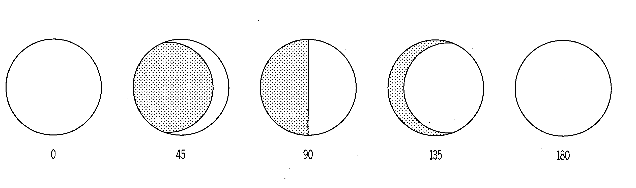
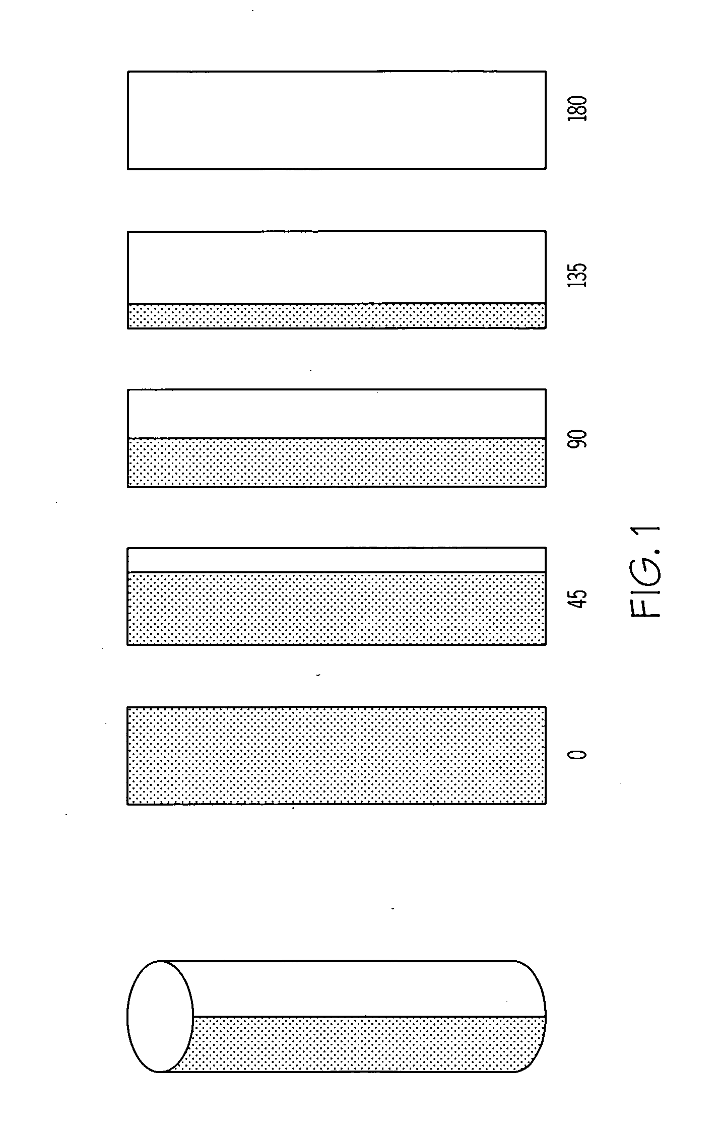
[0023] From the point of view of a thermal sensor, the variable emittance surfaces of the invention, enables an operator to choose the surface of an object from a continuum of treated surfaces with different spectral emittance and reflectance properties in fractions of a second. However, prior to describing the invention in detail, the theory of the invention must be described.

Theory

[0024] Suppose a plane target surface is normal to a sensor line of sight and half the detector footprint on a target falls entirely on a surface with emissivity ε1 and the other half falls on a surface with emissivity ε2. For this case the emittance seen by the detector is ½(ε1+ε2). More generally if the detector footprint has area A and area Ai of the footprint is on a surface with emissivity εi, then the effective emittance ε seen by the detector is given by ɛ=∑i=1n⁢ ⁢Ai⁢ɛi∑i=1n⁢ ⁢Ai(1)

[0025] Here the sum in the denominator equals the area A of the detector footprint. Equation (1) asserts the effec...


PUM


Abstract

Designs for constructing a surface with variable emittance are described. This is achieved by making a surface where the emissivity varies on a scale smaller than the resolution of a thermal imager viewing the surface. One design utilizes many cylindrical surfaces with their axis parallel and their surfaces nearly in contact. Individual cylinders have the property that when rotated to zero degrees they show a surface with an emissivity of one and when rotated to 180 degrees display a surface with an emissivity of zero. At intermediate angles of rotation a sensor that could resolve individual cylinders would see alternate lines with high and low emittance but a sensor unable to resolve individual cylinders sees a surface with an emittance that depends on the angle the cylinders are rotated. Variable emittance surfaces are expected to be useful for controlling target signature and for making spectral reflectivity measurements using a hyper-spectral radiometer.

Description

GOVERNMENT INTEREST [0001] The invention described herein may be manufactured, used, sold, imported, and / or licensed by or for the Government of the United States of America.FIELD OF INTEREST [0002] The invention relates to the remote detection of various objects via the object's emittance and more particularly, to varying the object's emittance to identify or camouflage them. BACKGROUND OF THE INVENTION [0003] Countermeasures to both visible and thermal sensors, such as camouflage and target signature reduction, have been of great importance in the modern battlefield. One typical infrared (IR) camouflage technique involves covering an object with a material cover, with or without environmentally controlled subsystems (having added extraordinary power requirements). Much effort has been expended in the determination of the materials to be used to comprise the typical IR camouflage covering. One example in the IR camouflage prior art may be found in U.S. Pat. No. 4,156,033 to Earl F....

Claims


Application Information

Patent Timeline
Patent Type & Authority Applications(United States)
IPC IPC(8): G01J5/00
CPCG02B26/02F41H3/00Y10S428/919
Inventor FRIEDMAN, MELVIN H.
Owner ARMY UNITED STATES OF AMERICA AS REPRESENTED BY DEPT OF THE
Why Eureka
Try Eureka