Coating device having coated transmitter coil

Pending Publication Date: 2020-04-23
AIXTRON AG
View PDF4 Cites 0 Cited by
  • Summary
  • Abstract
  • Description
  • Claims
  • Application Information

AI Technical Summary

Benefits of technology

[0010]The inventive coating has proved to be resistant to chlorine and chlorine-containing compounds on the one hand, and on the other hand has a low optical emissivity, that is to say, a high optical reflectivity. Moreover, the emissivity/reflectivity is stable over time. It does not change even after prolonged exposure of the coating to chlorine or a chlorine-containing compound, even at higher temperatures. The layer is highly resistant to chlorine ions and forms an effective diffusion ba

Problems solved by technology

A changing emissivity, e.g. due to oxide layers or reaction l

Method used


Image

  • Coating device having coated transmitter coil

Examples


Embodiment Construction

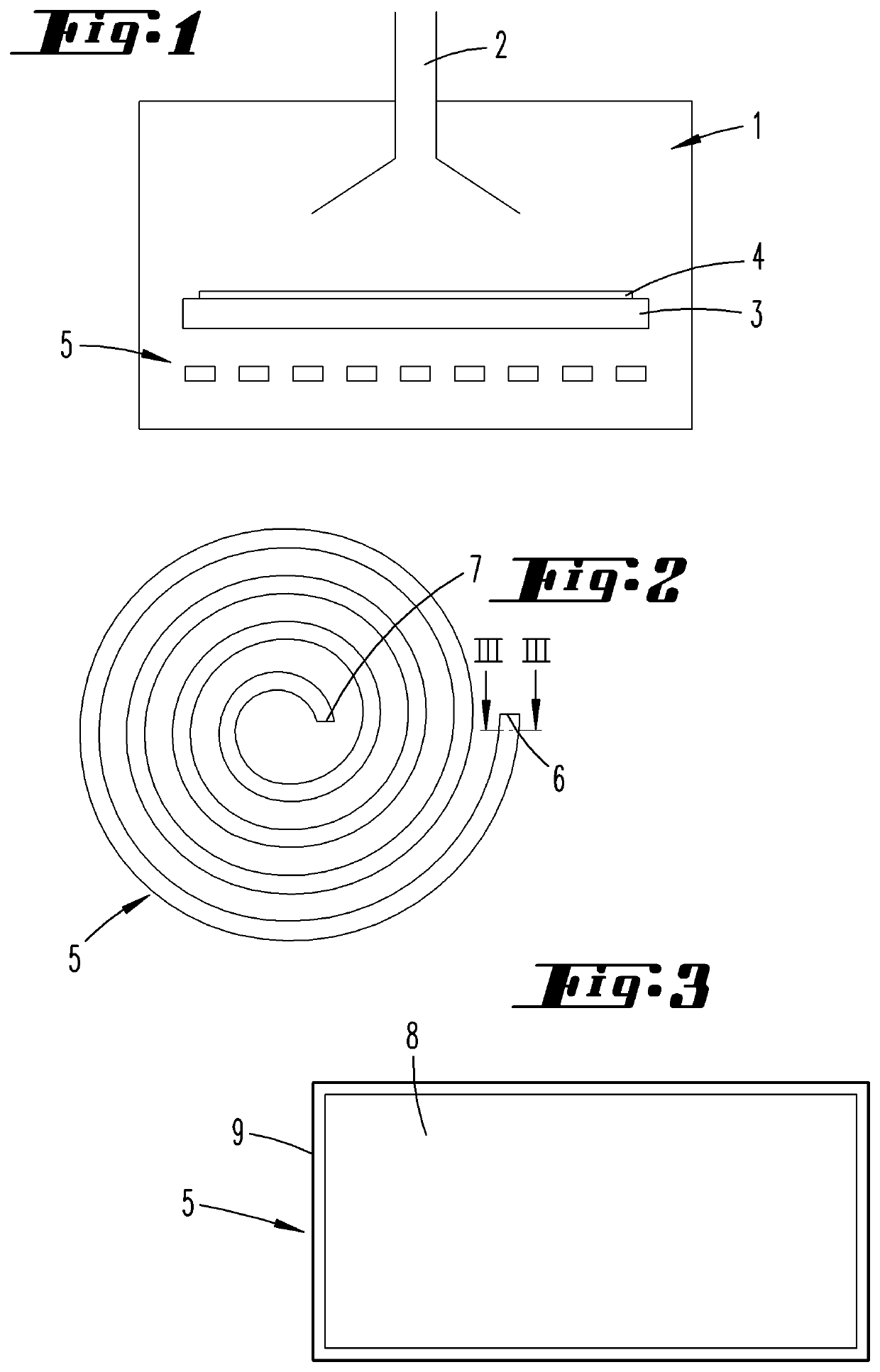
[0015]A gas-tight housing surrounds a process chamber 1, into which a gas inlet device 2 opens, through which (besides other precursors) chlorine-containing gases, for example chlorine-containing compounds of elements of the III-main group, are also supplied. However, other chlorine-containing compounds can also be supplied through the gas inlet device 2, for example so as to clean the process chamber 1 after a coating process by means of an etching step. Here Cl2 or HCl in particular can be considered as the gases.

[0016]In the process chamber 1 there is a susceptor 3, which consists of graphite or another electrically conductive material, and which bears one or a plurality of substrates 4, which are to be coated. In particular, they can be coated with a semiconductor layer, and in particular with a III-V semiconductor layer.

[0017]Underneath and in the same process chamber 1 a transmitter coil 5 is located, which is made of metal and has a spiral shape. The transmitter coil 5 has tw...


PUM

PropertyMeasurementUnit
Lengthaaaaaaaaaa
Lengthaaaaaaaaaa
Thicknessaaaaaaaaaa

Abstract

A device, for depositing a layer on a substrate by supplying one or more process gases to a process chamber, includes a susceptor and one or more transmitter coils. The susceptor bearing the substrate can be heated to a process temperature by means of an electromagnetic alternating field generated by the one or more transmitter coils. The one or more transmitter coils have a coating that consists of tin and nickel in order to provide a corrosion-resistant coating, which simultaneously has low emissivity and is therefore effective in the presence of chlorine compounds and moisture.

Description

RELATED APPLICATIONS[0001]This application is a National Stage under 35 USC 371 of and claims priority to International Application No. PCT / EP2018 / 067947, filed 3 Jul. 2018, which claims the priority benefit of DE Application No. 20 2017 104 061.5, filed 7 Jul. 2017.FIELD OF THE INVENTION[0002]The invention relates to a device for depositing a layer on a substrate by supplying one or a plurality of process gases into a process chamber, in which a susceptor bearing the substrate can be heated to a process temperature by means of an electromagnetic alternating field generated by one or a plurality of transmitter coils, wherein the one or a plurality of transmitter coils have a coating.BACKGROUND[0003]A device of this type is described in DE 10 2010 016 471 A1. A process chamber, in which a susceptor consisting of an electrically conductive material, on which a substrate rests, is located in a housing, which is sealed in a gas-tight manner relative to the environment. Reactive process ...

Claims


Application Information

Patent Timeline
IPC IPC(8): C23C16/46H05B6/10
CPCC23C16/46H05B6/105C25D7/0607C25D7/001C23C18/1653C23C16/4586C23C16/4581H01J37/32715
Inventor FUSS, HANS-GERD
Owner AIXTRON AG
Why Eureka
Try Eureka