Eureka AIR delivers breakthrough ideas for toughest innovation challenges, trusted by R&D personnel around the world.

Timing generator and methods thereof

a timing generator and control signal technology, applied in pulse manipulation, pulse technique, synchronisation signal speed/phase control, etc., can solve the problems of not being able to adapt to rf transceiver chips having different delay resolutions, conventional timing generators may only be capable of operation, and it is difficult to configure conventional timing generators to support different types of clock signals

Inactive Publication Date: 2007-02-15
SAMSUNG ELECTRONICS CO LTD
View PDF4 Cites 6 Cited by
  • Summary
  • Abstract
  • Description
  • Claims
  • Application Information

AI Technical Summary

Benefits of technology

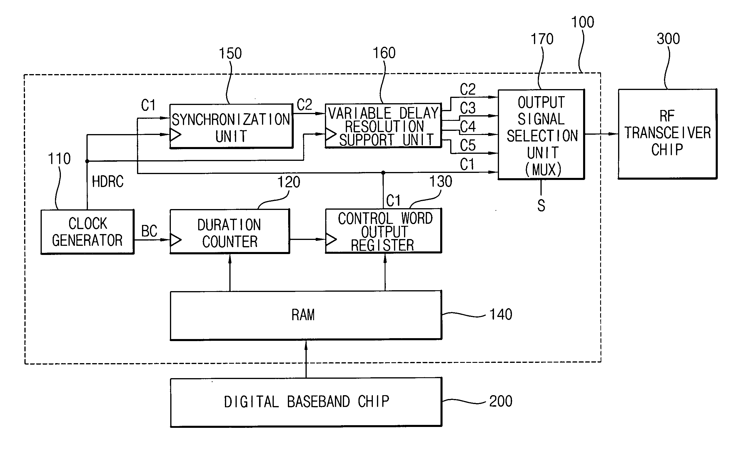
[0022] An example embodiment of the present invention is directed to a timing generator, including a clock generating unit configured to generate a base clock signal and a higher delay resolution signal, a clock cycle of the higher delay resolution signal being less than a clock cycle of the base clock signal, a control word output register configured to generate a first control word output signal by synchronizing a control word with the generated base clock signal, a synchronization unit configured to generate a second control word output signal by synchronizing the first control word output signal with the higher delay resolution clock signal and a variable delay resolution support unit configured to generate at least one additional control word output signal based on the second control word output signal and the higher delay resolution clock signal, the first, second and at least one additional control word output signals each having different delay resolutions.
[0023] Another example embodiment of the present invention is directed to a method of generating a timing control signal, including generating a base clock signal and a higher delay resolution clock signal, a clock cycle of the higher d

Problems solved by technology

However, because conventional timing generators may output the control word to a transceiver chip based upon an internally generated base clock signal, it may be difficult to configure a conventional timing generator to support different types of clock signals (e.g., because such signals may be generated “external” to the timing generator).
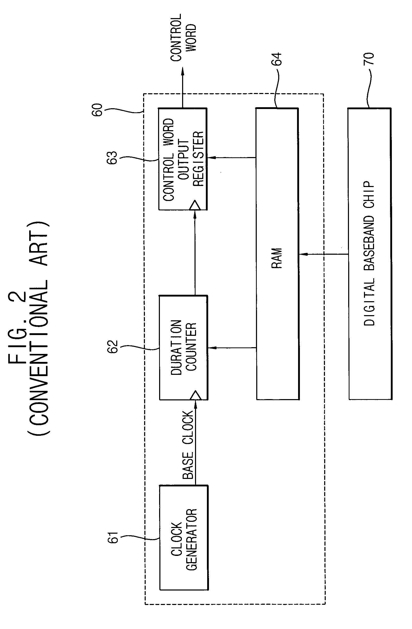
However, conventional timing generators may not be configured to adapt to RF transceiver chips having different delay resolutions, because the outputted control words may only be capable of being synchronized with the base clock signal, which may be generated internally at the timing generator (e.g., as shown in FIG. 2).
In other words, a conventional timing generator may only be capable of operation with an RF transceiver chip having a particular delay resolution.
For example, if a unit cycle (e.g., clock cycle or period) of the base clock signal generated in the timing generator is a ⅛ symbol clock and a unit cycle of the RF transceiver chip for transferring the control word is a 1 / 24 symbol clock, the timing generator may not support an optimal operation speed of the RF transceiver chip because the delay resolution of the operation clock for the RF transceiver chip may be three times higher than that of the base clock signal for the clock generator.
Such a redesign process is a laborious, time-consuming and expensive process.

Method used


Image

  • Timing generator and methods thereof
  • Timing generator and methods thereof
  • Timing generator and methods thereof

Examples


Embodiment Construction

[0031] Example embodiments of the present invention are described more fully hereinafter with reference to the accompanying drawings, in which example embodiments of the present invention are shown. Example embodiments of the present invention may, however, be embodied in many different forms and should not be construed as limited to the example embodiments set forth herein. Rather, these example embodiments are provided so that this disclosure will be thorough and complete, and will fully convey the scope of the invention to those skilled in the art. Like numbers refer to like elements throughout.

[0032] It will be understood that although the terms first and second are used herein to describe elements and should not be limited by these terms. These terms are used to distinguish one element from another. Thus, a first element discussed below could be termed a second region, layer or section, and similarly, a second element may be termed a first element without departing from the te...


PUM


Abstract

A timing generator and methods thereof are provided. In a first example method, a timing control signal may be produced by generating a base clock signal and a higher delay resolution clock signal, a clock cycle of the higher delay resolution signal being less than a clock cycle of the base clock signal. A first control word output signal may be generated by synchronizing a control word with the base clock signal. A second control word output signal may be generated by synchronizing the first control word output signal with the higher delay resolution clock signal and generating at least one additional control word output signal based on the second control word output signal and the higher delay resolution clock signal, the first, second and at least one additional control word output signal each having different delay resolutions. In a second example method, a timing control signal may be produced by generating a plurality of control word output signals, each of the plurality of control word output signals having a different delay resolution and selecting one of the plurality of control word output signals based on a delay resolution of the selected control word output signal, the delay resolution of the selected control word output signal better suited for interaction with an external device than delay resolutions of other of the plurality of control word output signals. A timing generator may be configured to perform either of the above-described first and second example methods.

Description

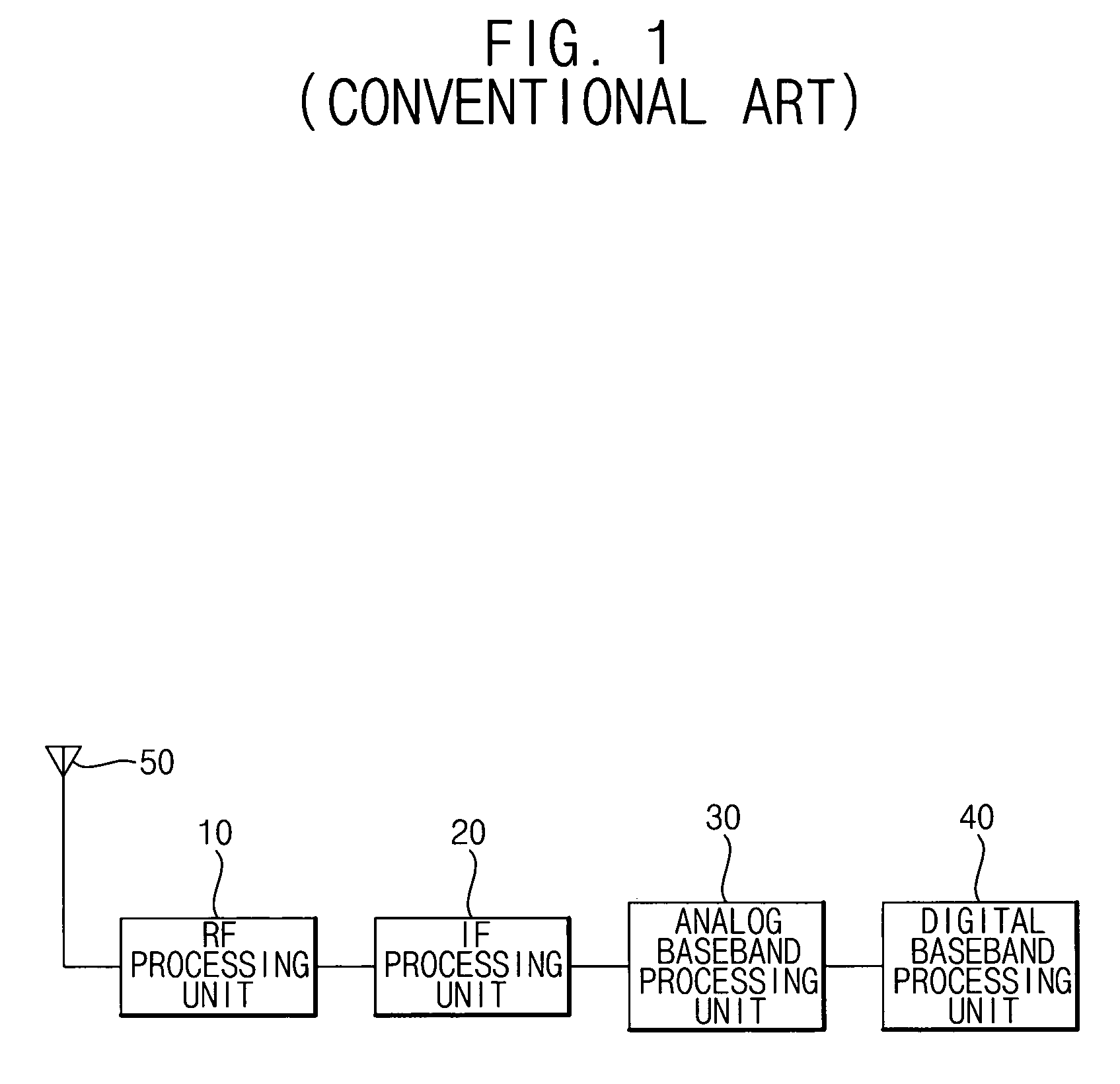
PRIORITY STATEMENT [0001] This application claims priority under 35 U.S.C. § 119 to Korean Patent Application No. 2005-73576 filed on Aug. 11, 2005, the contents of which is incorporated herein by reference in its entirety. BACKGROUND OF THE INVENTION [0002] 1. Field of the Invention[0003] Example embodiments of the present invention relate generally to a timing generator and methods thereof, and more particularly to a timing generator and methods of generating a timing control signal. [0004] 2. Description of the Related Art [0005] Conventional mobile communication systems (e.g., mobile phones, personal communication services (PCS), and personal digital assistants (PDAs), etc.) may be configured to support wireless communications. [0006]FIG. 1 is a block diagram illustrating a conventional wireless digital transceiver. Referring to FIG. 1, the conventional wireless digital transceiver may include an antenna 50, a radio frequency (RF) processing unit 10, an analog baseband processin...

Claims


Application Information

Patent Timeline
IPC IPC(8): H04L7/00H03K5/135H04B1/3822H04B1/40
CPCH04B1/40H04L7/10H04L7/00H04L7/08
Inventor KIM, KYOUNG-MAN
Owner SAMSUNG ELECTRONICS CO LTD
Why Eureka
Eureka Blog
Learn More