
Method and apparatus for severing root of bean sprout

a technology of bean sprouts and roots, applied in metal working devices, grain treatment, food shaping, etc., can solve the problems of difficult to remove bean sprouts from the upper layer of the pile, difficult to sever the root of the overall pile, and difficult to remove the overall pile root efficiently and cleanly. , to achieve the effect of efficiently severing

Active Publication Date: 2007-02-15
NAKADA MASAHIRO
View PDF2 Cites 1 Cited by
  • Summary
  • Abstract
  • Description
  • Claims
  • Application Information

AI Technical Summary

Benefits of technology

"The present invention provides a method and apparatus for severing roots of bean sprouts efficiently and cleanly. The severing table has ridges with severing slits that allow the roots of the bean sprouts to easily fall into the slits. Water or air is sprinkled or blown over the table to create a flow that helps the roots and leaves of the bean sprouts fall into the slits. The cutter blade is fitted with each ridge, so the bean sprouts are pushed onto the table while the cutter blade moves. The entire root of the bean sprout can be severed, and the leaves of the bean sprouts can also be efficiently severed. The severing table has flat portions between the ridges that allow for easy falling of the roots and leaves of the bean sprouts. The technical effects of this invention are efficient and clean severing of root and leaf parts of bean sprouts."

Problems solved by technology

Furthermore, when the bean sprouts on the severing table are scraped up by the cutter blade to be stacked, the bean sprouts of an upper layer of the pile are hard to fall into the severing slits and accordingly cannot be severed.
As a result, since the number of bean sprouts whose distal end slender portions of the roots have been severed is increased, it is difficult to sever overall roots of bean sprouts efficiently and cleanly.

Method used


Image

  • Method and apparatus for severing root of bean sprout
  • Method and apparatus for severing root of bean sprout
  • Method and apparatus for severing root of bean sprout

Examples


Embodiment Construction

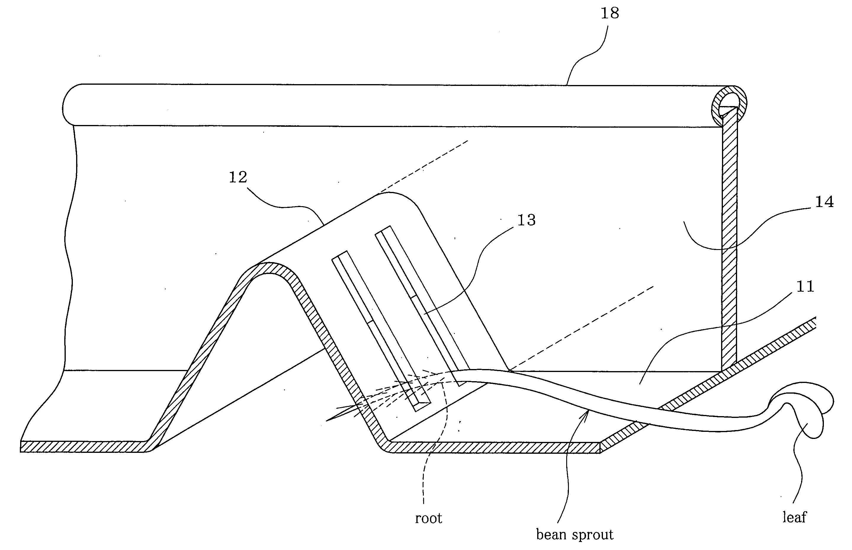
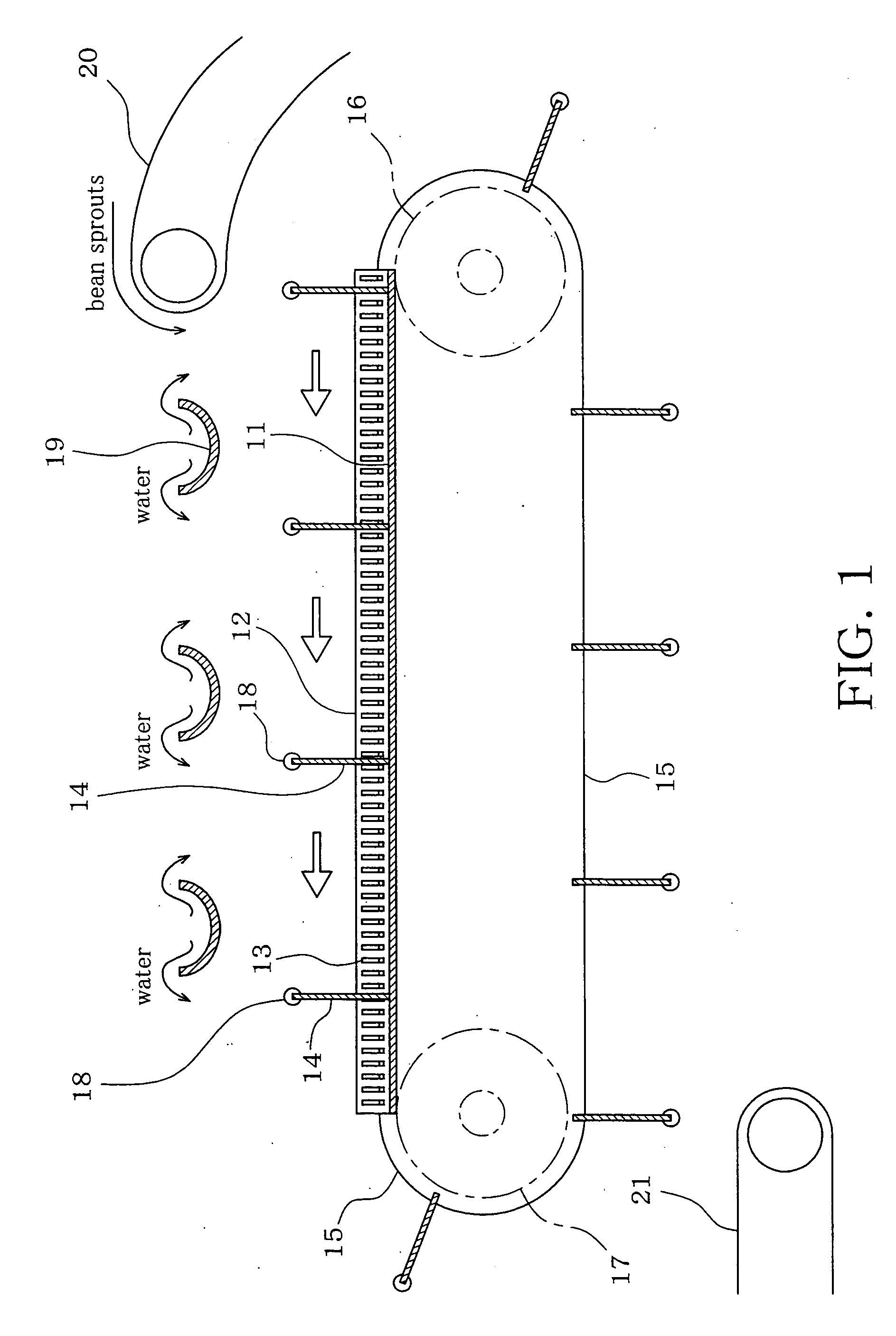
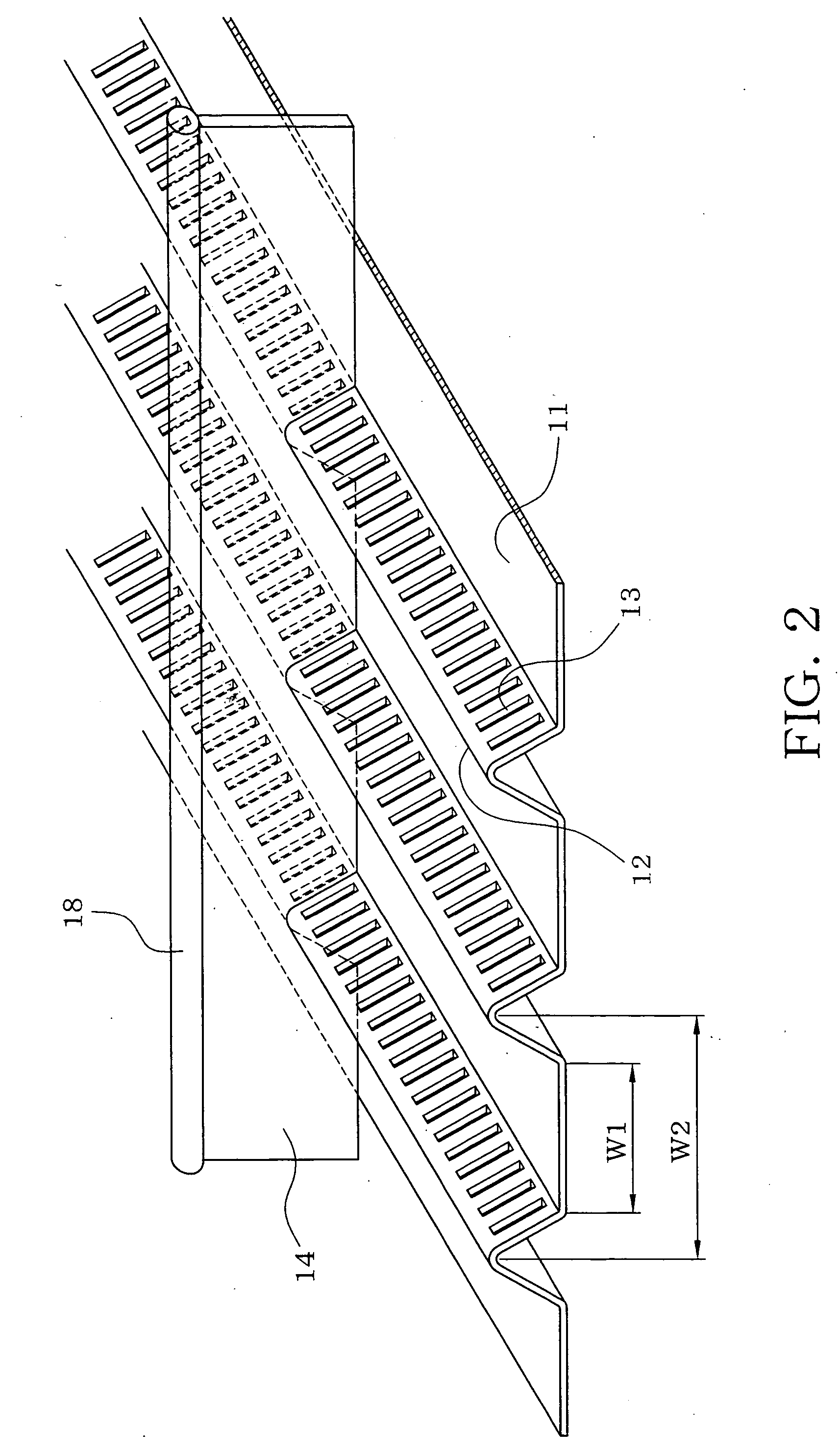
[0018] A first embodiment of the present invention will be described with reference to FIGS. 1 to 4. Firstly, the construction of the root severing apparatus will be described. The apparatus comprises a severing table 11 made by pressing a metal plate such as a stainless steel plate. The severing table 11 has a plurality of ridges 12 formed thereon at predetermined intervals and extending in parallel with a direction in which a cutter blade 14 which will be described later is moved. Each ridge 12 has a generally A-shaped section, for example. An apex of each ridge 12 is chamfered or rounded so that bean sprouts supplied from over each ridge easily slide it off. The section of each ridge 12 should not be limited to the A-shaped but may be formed into the shape of a curved convex such as an arcuate shape or an inverted U-shape.

[0019] Referring now to FIGS. 2 to 4, each ridge 12 has two inclined faces at both sides respectively. Each ridge 12 has a number of severing slits 13 formed t...


PUM


Abstract

In a method and apparatus for severing roots of bean sprouts, a severing table has a plurality of ridges formed at predetermined intervals and extending in parallel with a direction in which a cutter blade is moved. Each ridge is formed with a number of severing slits each of which has such a width that a root of a bean sprout falls into each severing slit. The bean sprouts are continuously supplied onto the severing table while a cutter blade is moved along an upper face of the severing table and water is being sprinkled over the severing table so that roots of the bean sprouts on the severing table flow into the severing slits. The roots of the bean sprouts fallen in the severing slits are severed by the cutter blade. The bean sprouts from which the roots have been severed are conveyed out of the severing table with movement of the cutter blade.

Description

CROSS-REFERENCE TO RELATED APPLICATION [0001] This application is a divisional of prior application number 10 / 807,640 filed on Mar. 23, 2004, now pending, pursuant to 35 U.S.C. § 121, and hereby incorporates that application by reference.BACKGROUND OF THE INVENTION [0002] 1. Field of the Invention [0003] The present invention relates to a method and apparatus for severing roots of bean sprouts. [0004] 2. Description of the Related Art [0005] Roots of bean sprouts harvested are recently cut off for improvement in their appearances and resultant increase in the commodity quality before the bean sprouts are bagged to be shipped. The inventor developed apparatus for severing roots of bean sprouts as disclosed in U.S. Pat. Nos. 6,346,288 and 6,379,732, in order to automate a work for cutting off bean sprouts. In these apparatus, bean sprouts are supplied onto a flat severing table and water is sprinkled onto the severing table so that while a cutter blade is moved along an upper side of ...

Claims


Application Information

Patent Timeline
Patent Type & Authority Applications(United States)
IPC IPC(8): A23P1/00A23N15/00B26D3/26B26D1/03B26D1/04B26D7/06
CPCA23N15/00B26D7/0625B26D1/04B26D1/03
Inventor NAKADA, MASAHIRO
Owner NAKADA MASAHIRO
Learn More