Endoscope balloon control device and abnormality determining method of the endoscope balloon control device
- Summary
- Abstract
- Description
- Claims
- Application Information
AI Technical Summary
Benefits of technology
Problems solved by technology
Method used
Image

Examples
embodiment 1
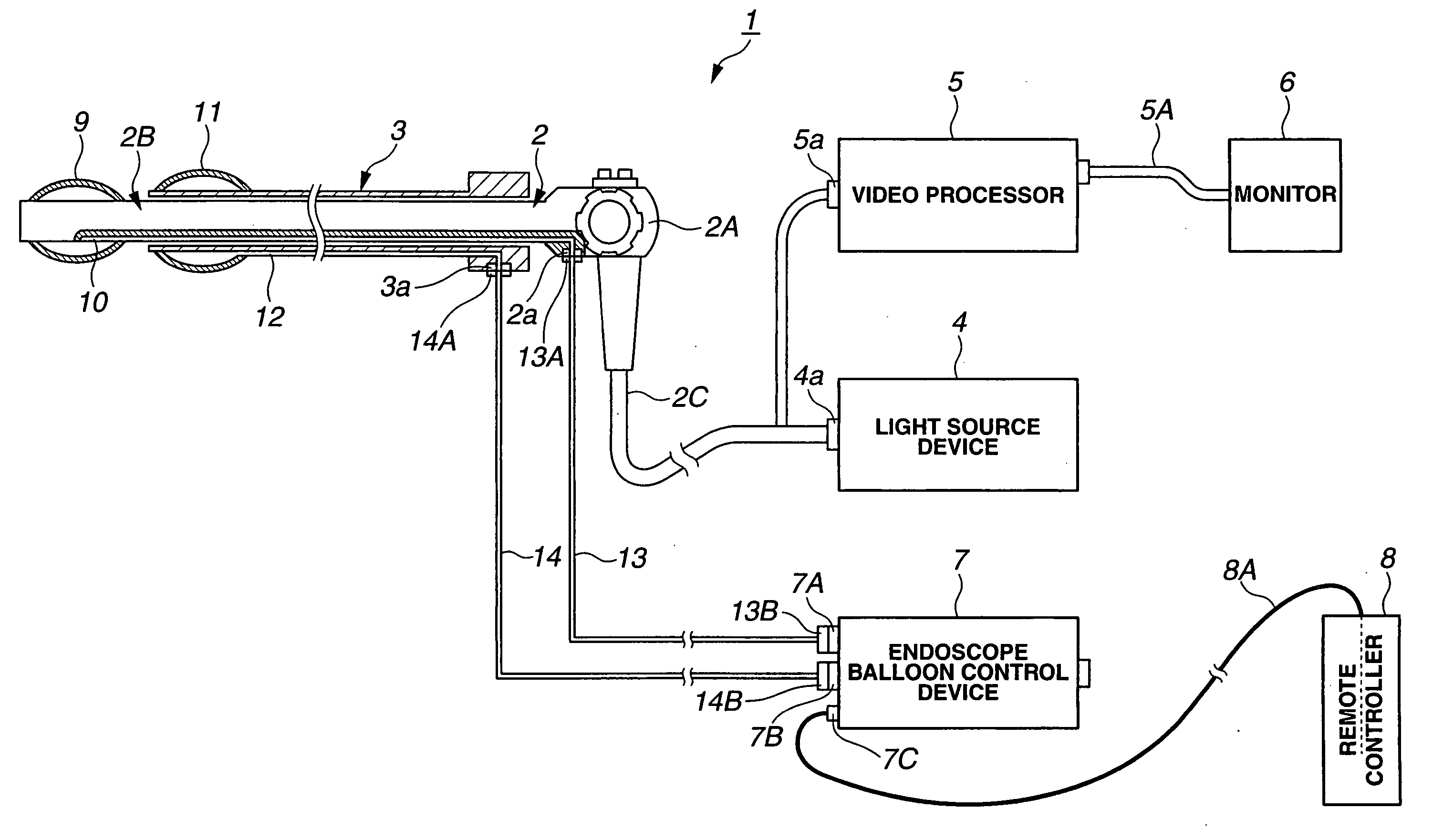
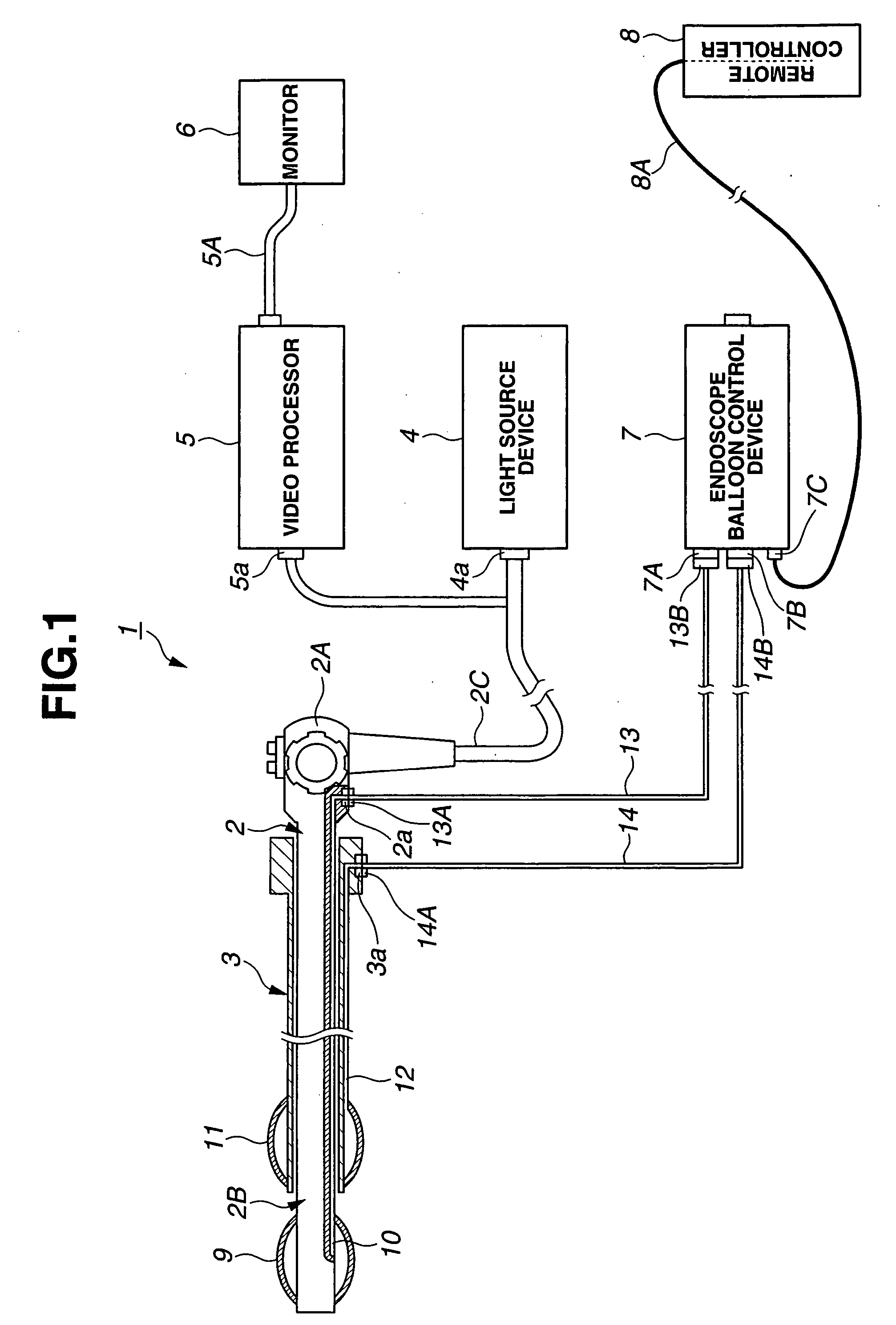
[0039]FIG. 1 is a configuration diagram showing an entire configuration of an endoscope system applied with an endoscope balloon control device according to a first embodiment of the present invention.
[0040] As shown in FIG. 1, an endoscope system 1 having an endoscope balloon control device of the embodiment has an endoscope 2, an overtube 3, a light source device 4, a video processor 5, a monitor 6, an endoscope balloon control device 7 and a remote controller 8.
[0041] The endoscope 2 is used for an alimentary canal endoscope examination, for example, having an inserting unit 2B to be inserted in a body cavity and an operation unit 2A provided at a rear anchor side of the inserting unit 2B. An observation optical system including an illumination optical system and a CCD which is an image pickup device (not shown) is provided in the tip part of the inserting unit 2B and illuminates an observed part in the alimentary canal of a subject body and can obtain an observation image in t...
embodiment 2
[0155] Next, an endoscope balloon control device according to the second embodiment will be described with reference to FIG. 16 to FIG. 22.
[0156] From FIG. 16 to FIG. 22 relate to the embodiment 2; FIG. 16 is a configuration diagram showing an outlined configuration of an endoscope balloon control device of the second embodiment; FIG. 17 is a block diagram showing an inner configuration of the endoscope balloon control device of FIG. 16; FIG. 18 is a flowchart showing control contents of an endoscope balloon control device according to the second embodiment; FIG. 19 is a graph showing relationship between an inner pressure of a duct and a gas sending time when it is determined as abnormal adjustment ending information in the minimum amount of flow setting of a pump in a flowchart of FIG. 18; FIG. 20 is a graph showing relationship between an inner pressure of a duct and a gas sending time when it is determined as abnormal adjustment ending information in the maximum amount of flow ...
PUM
 Abstract
Description
Claims
Application Information
 - R&D
- Intellectual Property
- Life Sciences
- Materials
- Tech Scout
- Unparalleled Data Quality
- Higher Quality Content
- 60% Fewer Hallucinations
Browse by: Latest US Patents, China's latest patents, Technical Efficacy Thesaurus, Application Domain, Technology Topic, Popular Technical Reports.
© 2025 PatSnap. All rights reserved.Legal|Privacy policy|Modern Slavery Act Transparency Statement|Sitemap|About US| Contact US: help@patsnap.com