Automated quoting of CNC machined custom molds and/or custom parts

a technology of cnc machined custom molds and custom parts, applied in the field of custom parts manufacturing, can solve the problems of cnc machining being rarely used, affecting the quality of custom parts, and requiring more time and expense for custom fixturing, so as to achieve flexibility and interactivity.

Inactive Publication Date: 2007-02-15
PROTOLABS INC
View PDF16 Cites 61 Cited by
  • Summary
  • Abstract
  • Description
  • Claims
  • Application Information

AI Technical Summary

Benefits of technology

The present invention is a method and system for automatically generating a custom quote for making a custom part or mold. The system analyzes the surface profile of the part and determines certain cost-related parameters, and then generates a flexible and interactive quote based on those parameters. This allows the customer to see how the part changes at different levels of the quote. The technical effect of this invention is to make the manufacturing process more efficient and cost-effective by automating the process of generating a custom quote.

Problems solved by technology

The technical problem addressed in this patent text is how to efficiently and accurately communicate about manufacturable issues faced when making molds and parts using traditional methods. The current state of art involves multiple steps and interactions between the customer and the moldmaker/machiner, resulting in slow decision-making processes and increased risk of error. There is a need for better ways to visually inspect and analyze the design of molds and parts, allowing them to improve faster and reduce risks associated with injected molded parts.

Method used


Image

  • Automated quoting of CNC machined custom molds and/or custom parts
  • Automated quoting of CNC machined custom molds and/or custom parts
  • Automated quoting of CNC machined custom molds and/or custom parts

Examples


Embodiment Construction

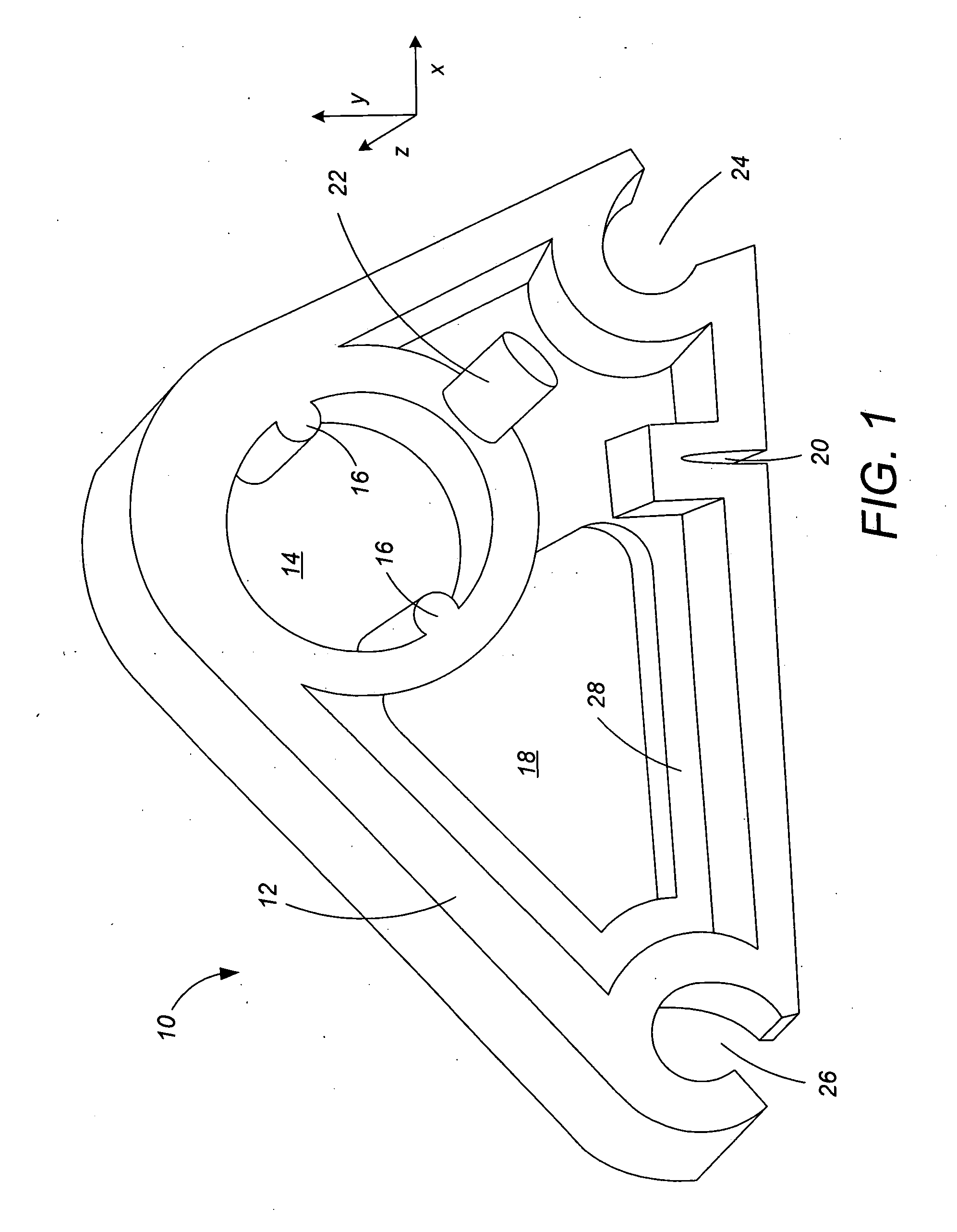
[0036] The present invention will be described with reference to an exemplary part 10 shown in FIG. 1. FIG. 1 represents a “cam” part 10 designed by the customer. In part because the cam 10 is custom-designed (i.e., not a staple article of commerce) by or for this particular customer, the cam 10 includes numerous features, none of which have commonly accepted names. For purposes of discussion, we will give names to several of these features, including a part outline flange 12, a circular opening 14 with two rotation pins 16, a non-circular opening 18, a notch 20, a rib 22, a 60° corner hole 24, a 30° corner hole 26, and a partial web 28. However, workers skilled in the art will appreciate that the customer may in fact have no name or may have a very different name for any of these features.

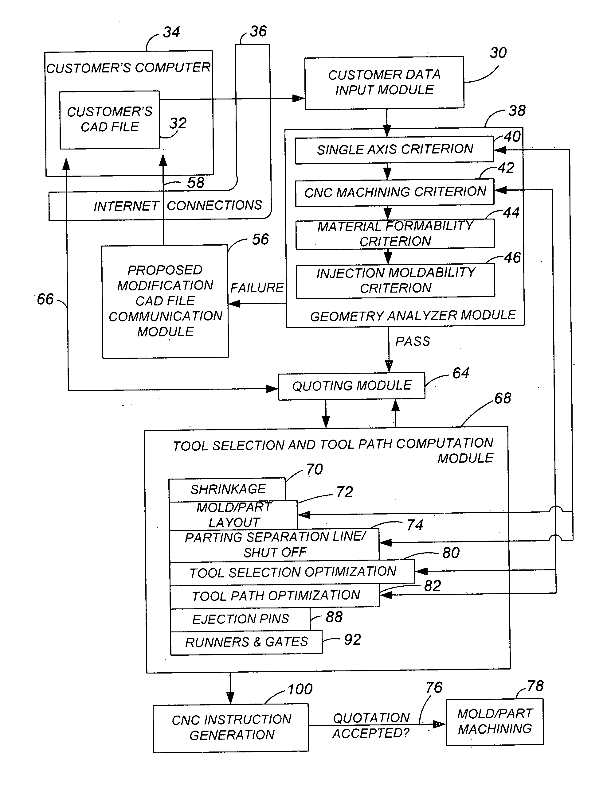
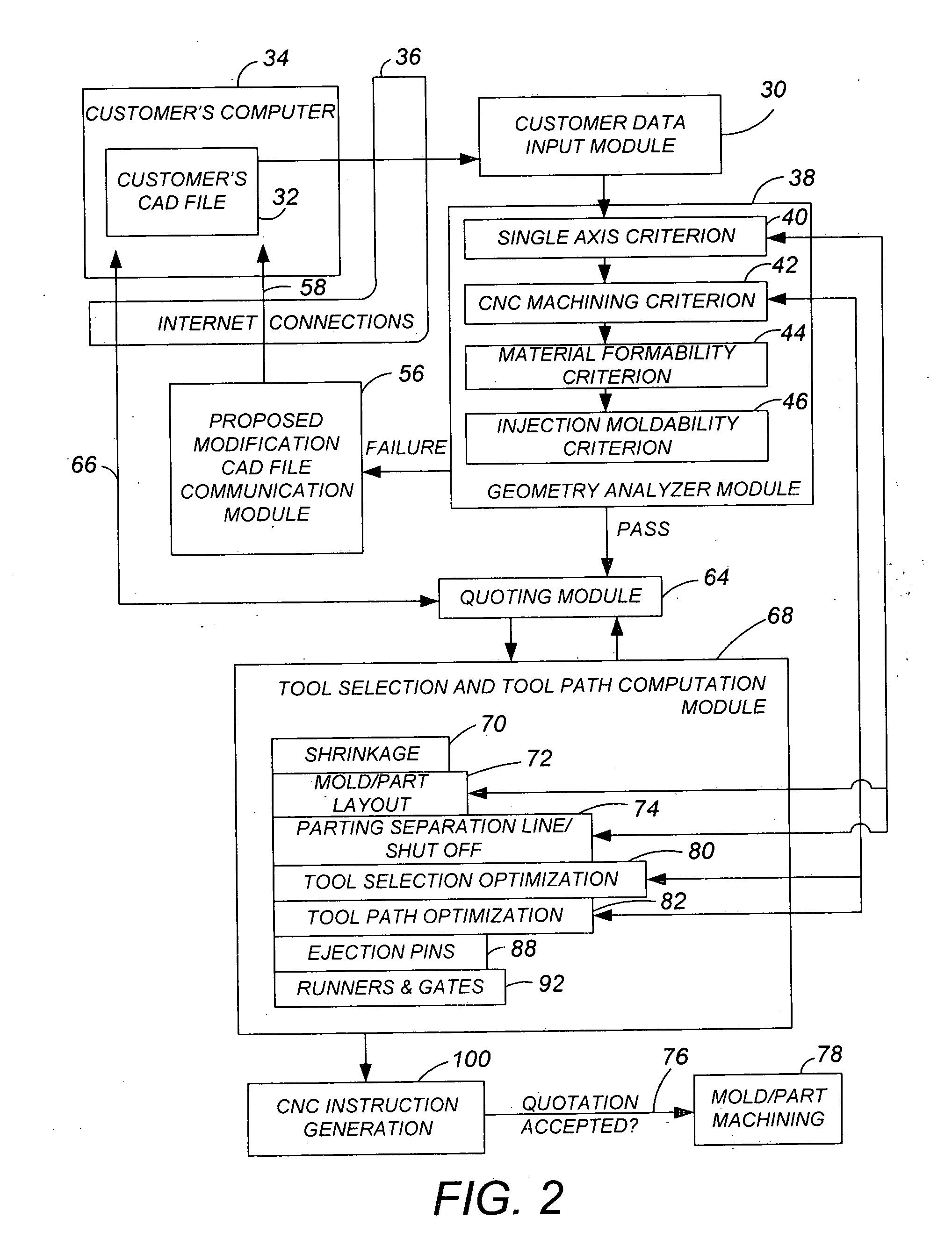
[0037]FIG. 2 is a flow chart showing how the present invention is used to manufacture the customer's part. The first step involves a Customer Data Input module 30. A starting input for the presen...


PUM


Abstract

A customer sends a CAD file for the part to be manufactured to the system. The system assesses the CAD file to determine various pieces of manufacturing information. One or more acceptability criteria are applied to the part, such as whether the part can be machined in two opposing orientations in a 3 axis CNC machine. If not, the system sends a file to the customer graphically indicating which portions of the part need modification to be manufacturable. The system provides the customer with a quotation form, that allows the customer to select several parameters, such as number of cavities or parts per workpiece block, surface finish and material, which are independent of the shape of the part. The quotation module then provides the customer with the cost to manufacture the mold or a number of parts, which may include both molded parts and total profiled machined parts. Budget-driven quotation is possible, wherein proposed modifications in the molding process are controlled by the budget of the customer. Interactivity is also achieved, with the customer being able to modify the quotation interactively by modifying one or more of the initially selected parameters, including selecting a different budgeted amount.

Description


Claims


Application Information

Patent Timeline
Owner PROTOLABS INC
Why Eureka
Try Eureka