Reduced stress relaxation in elastomeric compression structures adapted for use with electrical components

a compression structure and elastomeric technology, applied in the direction of coupling device connection, instruments, computing, etc., can solve the problems of reducing the stress relaxation of the compression structure or mat, affecting the actuation load required to compress the compression fingers, and faulty connections, so as to reduce the stress relaxation of the loaded formulation, reduce the negative effect, and reduce the stress relaxation

Inactive Publication Date: 2007-02-15
IBM CORP
View PDF6 Cites 2 Cited by
  • Summary
  • Abstract
  • Description
  • Claims
  • Application Information

AI Technical Summary

Benefits of technology

[0006] The present invention provides enhanced methods and structures that are for reducing stress relaxation issues and that are particularly adapted for use in electrical connections without negative effect.
[0007] Aspects of the present invention include embodiments for enhanced methods and structures for forming an elastomeric compression structure. The methods and structures comprise providing a formulation including a base elastomer and a plurality of gas-expandable members dispersed within the base elastomer, wherein the gas-expandable members remain substantially unexpanded while the formulation is cured in a predefined curing temperature range; loading the cured formulation under compression and, heating the loaded formulation to operating temperatures in which the loaded formulation operates to cause the base elastomer and the gas-expandable members to expand by an amount sufficient to reduce stress relaxation of the loaded formulation.

Problems solved by technology

Connectors of this latter type have a drawback in that the elastomeric materials of the compression structure or mat have a tendency to relax after the clamping arrangement has been tightened to a desired state.
The relaxation of the material reduces the pressure forcing the contact members against the connector fingers, and thus may lead to faulty connections.
However, as the hardness of an elastomeric compression structure or mat increases, so does the actuation load required to compress the compression fingers to the necessary degree.
Furthermore, attempts might be made to shorten the compression fingers in an attempt to minimize stress relaxation, but short, compression fingers pose reliability concerns due to assembly tolerance stack (e.g., compression fingers that are not quite long enough but are still within tolerance may not press the contact members against the contact fingers with sufficient force to ensure a reliable connection).

Method used


Image

  • Reduced stress relaxation in elastomeric compression structures adapted for use with electrical components
  • Reduced stress relaxation in elastomeric compression structures adapted for use with electrical components
  • Reduced stress relaxation in elastomeric compression structures adapted for use with electrical components

Examples


Embodiment Construction

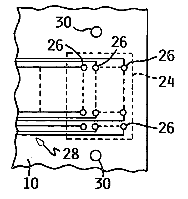
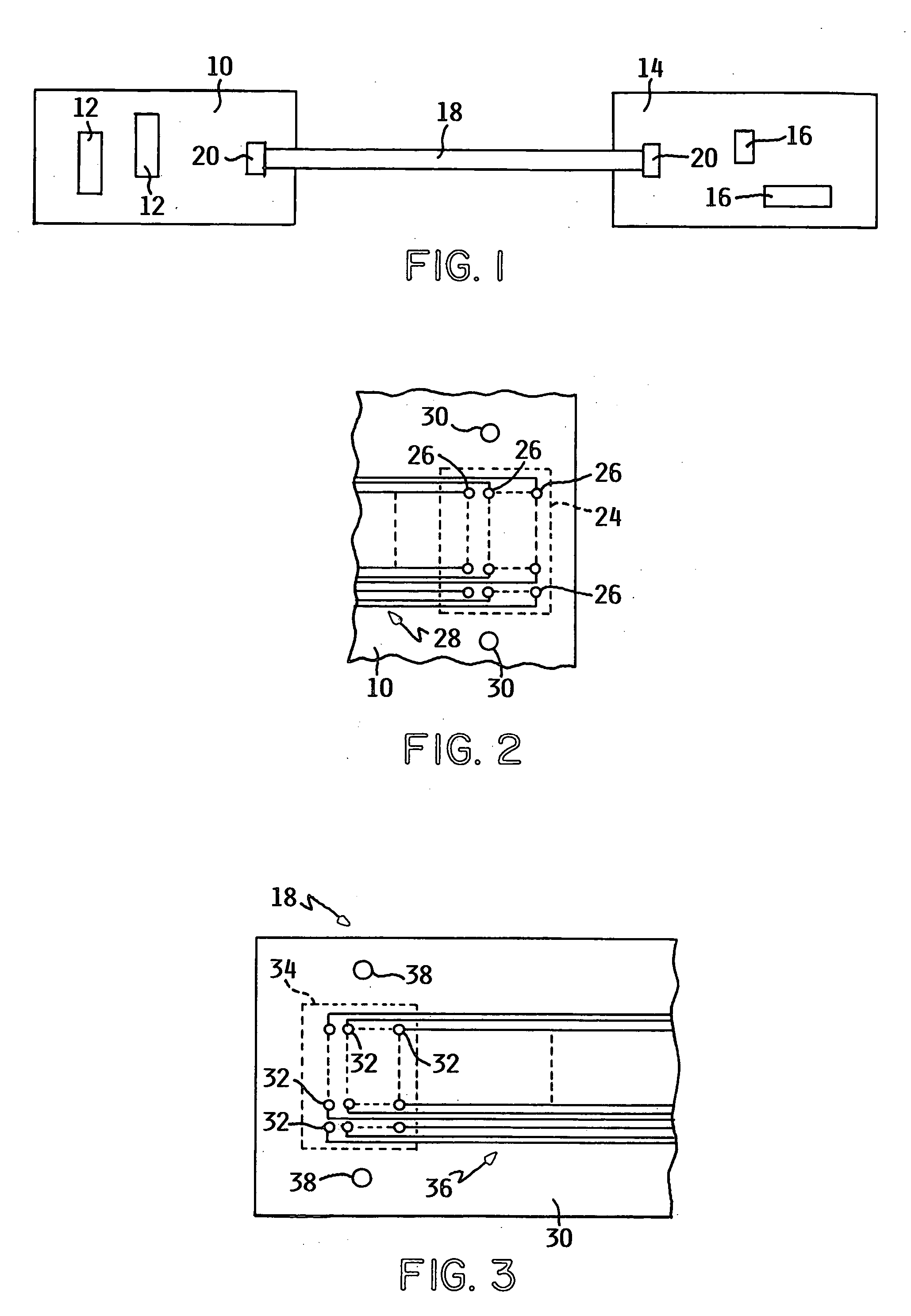
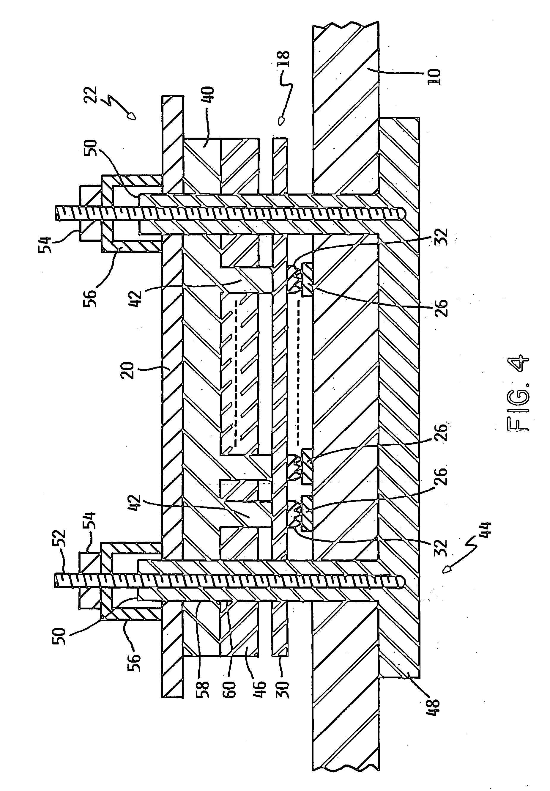
[0017] One preferred embodiment of the present invention is directed to an improved connector that can be used, for example, to connect a ribbon cable to contact fingers on an integrated circuit board. However, as will be pointed out, other compression structures are envisioned that may be particularly adapted to electrical connectors. FIG. 1 illustrates a first printed circuit board 10 having circuitry, such as integrated circuits 12 and a second printed circuit board 14 having circuitry, such as integrated circuits 16. A ribbon cable 18 having a plurality of parallel conductors (not shown in FIG. 1) carries signals between the circuitry of the first and second printed circuit boards 10 and 14, respectively. A clamping plate 20 of a connector 22 (see FIG. 4) connects the one end of ribbon cable 18 to the integrated circuits 16 on printed circuit board 10. Similarly, the other end of cable 18 is connected to the circuitry on the printed circuit board 14 by a connector 22 that includ...


PUM


Abstract

Disclosed are enhanced methods and elastomeric compression structures utilizing embedded gas-filled gas-filled polymeric microspheres that are expanded in predefined conditions that are usable in electrical components for reducing stress relaxation.

Description

BACKGROUND OF THE INVENTION [0001] The present invention is directed generally towards methods and structures used for minimizing and / or eliminating stress relaxation, particularly in elastomeric compression structures that are particularly adapted for use with electrical components. [0002] Connectors are in widespread use in the electronics industry. One class of electrical connectors uses contact members on a ribbon cable. The contact members are pressed against contact fingers on a printed circuit board. Pressure is exerted on the back of the ribbon cable by an elastomeric compression structure or mat having compression fingers that are aligned with the contact members and contact fingers. The compression structure or mat is clamped to the printed circuit board. The compression structure or mat and its compression fingers are made of elastomeric materials, and the compression fingers act somewhat as springs. When the clamping arrangement is tightened, the compression fingers are ...

Claims


Application Information

Patent Timeline
Patent Type & Authority Applications(United States)
IPC IPC(8): G06F13/28
CPCH01R43/007H01R13/2414
Inventor KUCZYNSKI, JOSEPHSPLITTSTOESSER, KEVIN ALBERTTOFIL, TIMOTHY JEROMEVERMILYEA, PAUL ALAN
Owner IBM CORP
Why Eureka
Try Eureka