Cyclone dust collecting apparatus for vacuum cleaner

a vacuum cleaner and dust collection technology, applied in the field of vacuum cleaners, can solve the problems of reducing the dust collection efficiency, re-scattered collected contaminant, and load applied to the vacuum generation source, and achieve the effect of reducing the noise and pressure loss caused by the turbulent flow generated in the grill uni

Inactive Publication Date: 2007-02-22
SAMSUNG GWANGJU ELECTRONICS CO LTD
View PDF7 Cites 41 Cited by
  • Summary
  • Abstract
  • Description
  • Claims
  • Application Information

AI Technical Summary

Benefits of technology

[0030] In addition, according to the cyclone dust collecting apparatus for the vacuum cleaner of the present invention, the purified air from which the contaminant is separated by a centrifugal force generated by the whirling helical vortex current is passed through the grill unit. In this manner, the contaminant remaining in the purified air is removed by the lattice member and the flow of the purified air is stabilized by the plurality of air-guiding members so that the pressure loss and noise caused by a turbulent flow generated in the grill unit is reduced. According to the present invention, accordingly, since the pressure loss caused by the turbulent flow is reduced, a load applied to a vacuum generating source is reduced, and so the electrical power required for driving the dust collecting apparatus for the vacuum cleaner can be saved.

Problems solved by technology

However, since the contaminant receptacle 7 functions as both roles for separating and collecting the contaminant, such conventional cyclone dust collecting apparatus 1 for the vacuum cleaner has the problems that the dust collection efficiency decreases and the collected contaminant is re-scattered.
Therefore, the above cyclone dust collecting apparatus has the problem that, if the pressure loss is generated in the air discharge tube 6, a load applied to a vacuum generation source (not shown) is increased, and so the power consumption becomes large.
Accordingly, the above cyclone dust collecting apparatus has the problem that, once the flow rate of air is rapidly increased as described, the noise becomes large.

Method used


Image

  • Cyclone dust collecting apparatus for vacuum cleaner
  • Cyclone dust collecting apparatus for vacuum cleaner
  • Cyclone dust collecting apparatus for vacuum cleaner

Examples


first embodiment

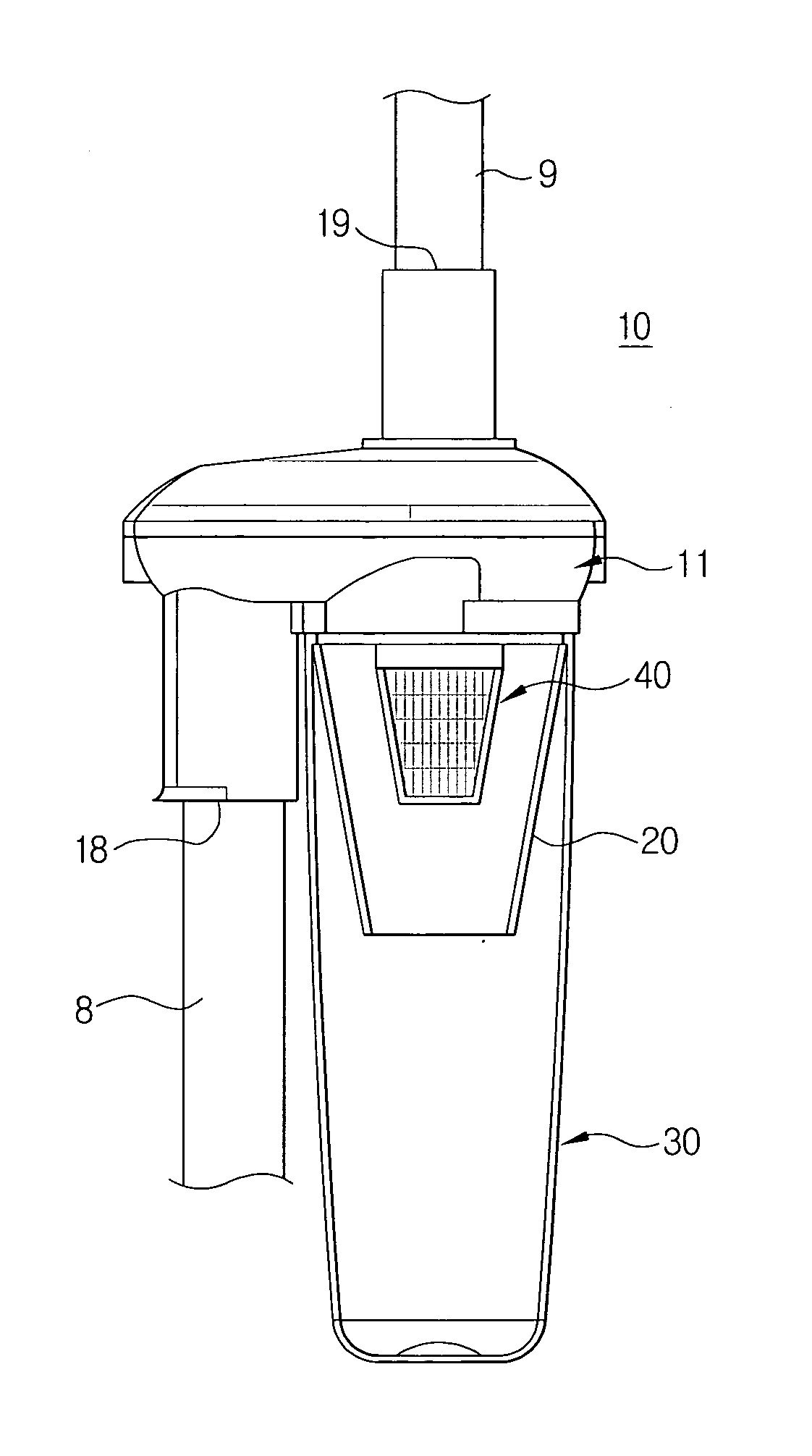
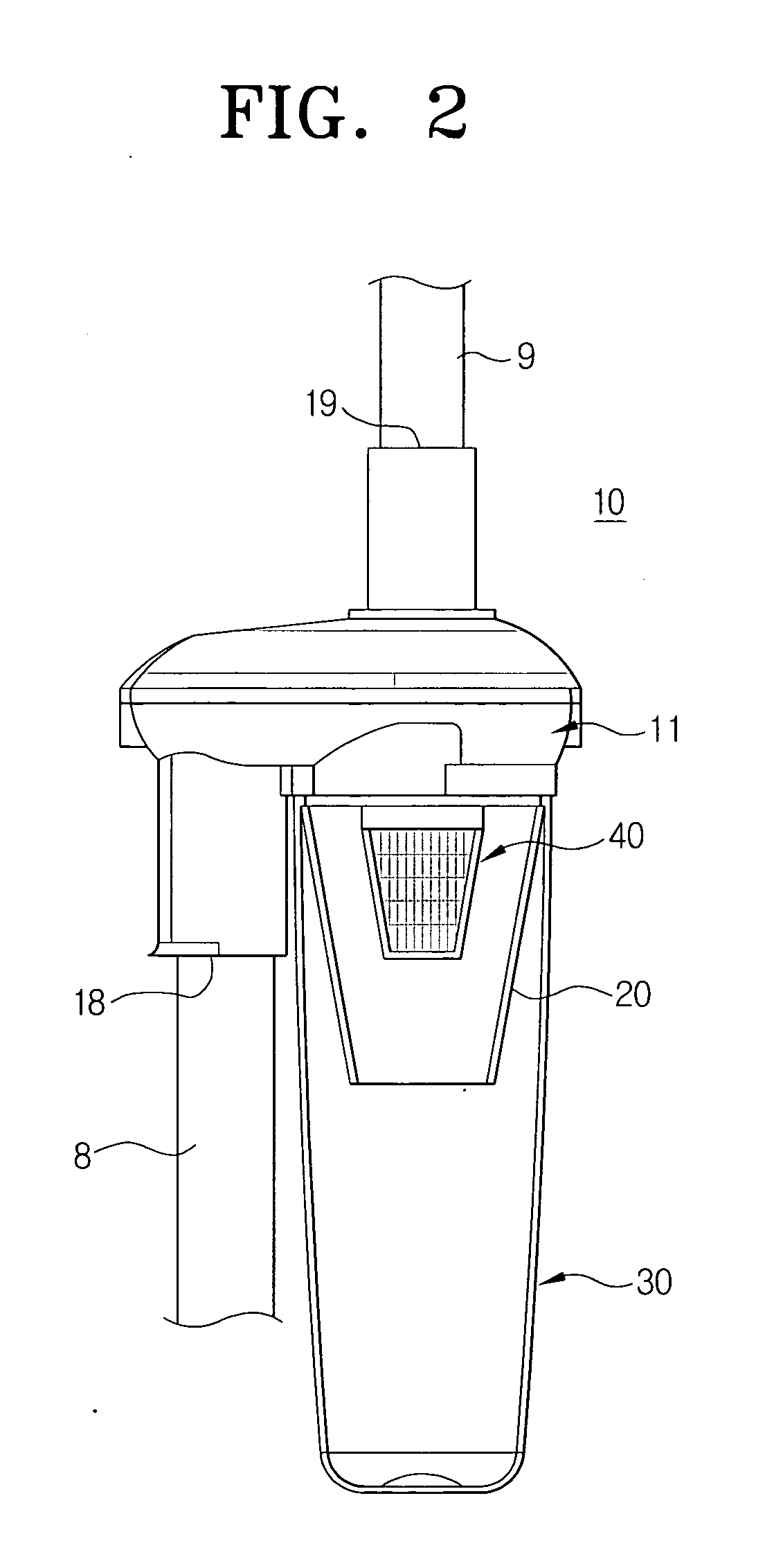
[0044] Referring to FIG. 2 and FIG. 3, a cyclone dust collecting apparatus 10 for a vacuum cleaner according to the present invention is provided. Cyclone dust collecting apparatus 10 comprises a cyclone body 11, a grill unit 40, an inner cover 20, and a contaminant receptacle 30.

[0045] The cyclone body 11 is provided between a first extension tube 8 and a second extension tube 9 and comprises a side wall 12, an air suction passage 13, an air discharge tube 19, and an upper cover 15.

[0046] The side wall 12 forms a main frame of the cyclone body 11 and has a hollow cylindrical shape. In cooperation with the upper cover 15 and the inner cover 20, the side wall forms a portion of a whirling space S (see FIG. 3) in which contaminant-laden air X sucked in the cyclone body 11 and containing contaminants is rotated.

[0047] An air suction tube 18 is formed at a side of the side wall 12 and is parallel with the side wall12. The air suction tube 18 functions as an inlet through which the con...

second embodiment

[0057] Below, according to another aspect of the present invention, the cyclone dust collecting apparatus according to the present invention is described with reference to FIG. 4 and FIG. 5.

[0058] Referring to FIG. 4 and FIG. 5, a cyclone dust collecting apparatus 10′ according to the second embodiment of the present invention comprises the cyclone body 11, the grill unit 40, a backflow preventing member 50, the inner cover 20, and the contaminant receptacle 30.

[0059] The grill unit 40 is installed at a lower end of the air discharge tube 19 and has an approximately hollow truncated cone that is smaller than the inner cover 20 in size. A plurality of grill holes 41 is formed on the grill unit 40. These grill holes 41 separate the contaminant contained in the purified air Y to be discharged.

[0060] The backflow preventing member 50 is provided to prevent the contaminant collected in the contaminant receptacle 30 from backflowing through the opened lower end 22 of the inner cover 20....

third embodiment

[0068] Below, according to another aspect of the present invention, the cyclone dust collecting apparatus according to the present invention is described with reference to accompanied FIG. 6 to FIG. 9.

[0069] Referring to FIG. 6 to and FIG. 9, a cyclone dust collecting apparatus 60 according to the third embodiment of the present invention comprises the cyclone body 11, a grill unit 100 and the contaminant receptacle 30.

[0070] The cyclone dust collecting apparatus 60 according to this embodiment of the present invention is characterized in that the grill unit 100 installed at a lower end of the air discharge tube 19 of the cyclone body 11 and having a function for filtering the contaminant contained in the purified air being discharging and a function for stabilizing the air discharged to the air discharge tube 19.

[0071] The grill unit 100 as described above includes a grill body 101, a lattice member 104, and a plurality of air-guiding members 105.

[0072] The grill body 101 is com...


PUM

PropertyMeasurementUnit
shapeaaaaaaaaaa
diameteraaaaaaaaaa
suction forceaaaaaaaaaa

Abstract

The present invention is a cyclone dust collecting apparatus for a vacuum cleaner in which an air-whirling space and a contaminant collecting space are separated from each other. The cyclone dust collecting apparatus for the vacuum cleaner according to the present invention comprises a cyclone body connected to an extension tube; an inner cover provided at a lower side of the cyclone body, the inner cover having a hollow conical shape with an opened upper and lower ends; a grill unit through which the air is discharged, the grill unit being provided at a lower end of an air discharge tube of the cyclone body in the inner cover; and a contaminant receptacle for receiving a contaminant fallen from the inner cover, the contaminant receptacle being provided at a lower side of the inner cover.

Description

CROSS-REFERENCE TO RELATED APPLICATIONS [0001] This application claims benefit under 35 U.S.C. § 119(a) of Korean Patent Application No. 2005-76931, filed Aug. 22, 2005, the entire contents of which are incorporated herein by reference. BACKGROUND OF THE INVENTION [0002] 1. Field of the invention [0003] The present invention relates to a vacuum cleaner. More particularly, the present invention relates to a cyclone dust collecting apparatus for a vacuum cleaner. [0004] 2. Description of the Related Art [0005] The vacuum cleaner is an apparatus for sucking air, dust and contaminant using a suction force generated by a motor. Accordingly, the vacuum cleaner is provided with a dust collecting apparatus for separating dust or dirt and the like (hereinafter, referred to as “contaminant”) from the sucked air and collecting them. To this end, the various types of dust collecting apparatuses have been used in the vacuum cleaner. In recent, a cyclone dust collecting apparatus has been widely ...

Claims


Application Information

Patent Timeline
Patent Type & Authority Applications(United States)
IPC IPC(8): B01D50/00
CPCA47L9/1658B04C5/181B04C5/13B01D45/16A47L9/00A47L9/16
Inventor OH, JANG-KEUNLEE, HAK-BONG
Owner SAMSUNG GWANGJU ELECTRONICS CO LTD
Why Eureka
Try Eureka