Frictional characteristic measuring apparatus and tire directed thereto

a technology of frictional characteristic and measuring apparatus, which is applied in the direction of specific gravity measurement, instruments, and ways, etc., can solve the problems of not being able to perform a 100% inspection, not being able to perform a deterioration test of a product in use, and being unable to measure the frictional characteristic of the object to be measured while the object remains inta

Inactive Publication Date: 2007-02-22
ORMON CORP
View PDF0 Cites 35 Cited by
  • Summary
  • Abstract
  • Description
  • Claims
  • Application Information

AI Technical Summary

Benefits of technology

[0033] According to embodiments of the present invention, the sensor section can be brought into contact with the object to be measured to measure a viscoelastic characteristic of the object to be measured, so as to calculate a frictional characteristic based upon the measured viscoelastic characteristic. Hence there is no need for production of a test specimen as has been conventionally necessary. It is therefore possible to realize the frictional characteristic measuring apparatus capable of measuring the frictional characteristic of the object to be measured at high speed in a non-destructive manner.

Problems solved by technology

This has necessitated cutting of the test specimen from the object to be measured, making it impossible to measure the frictional characteristic of the object to be measured while the object remains intact.
Further, using the conventional measurement apparatus, it has not been possible to perform the deterioration test of a product in use because the target to be measured has been destroyed.
Moreover, in the conventional measurement apparatus, it has not been possible to perform a 100% inspection in the pre-shipment test, and hence a scanning inspection has inevitably been performed.

Method used


Image

  • Frictional characteristic measuring apparatus and tire directed thereto
  • Frictional characteristic measuring apparatus and tire directed thereto
  • Frictional characteristic measuring apparatus and tire directed thereto

Examples


embodiment 1

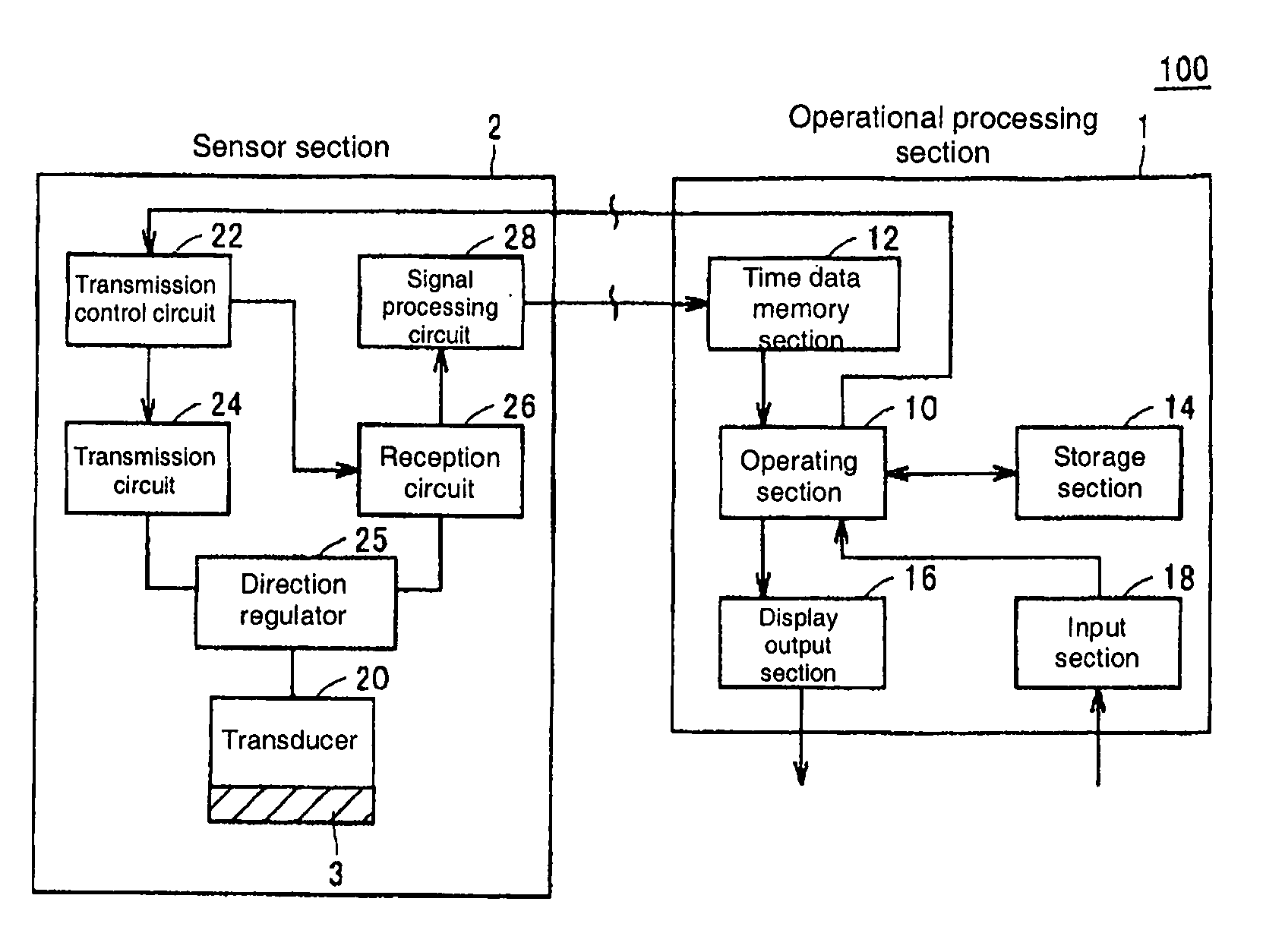
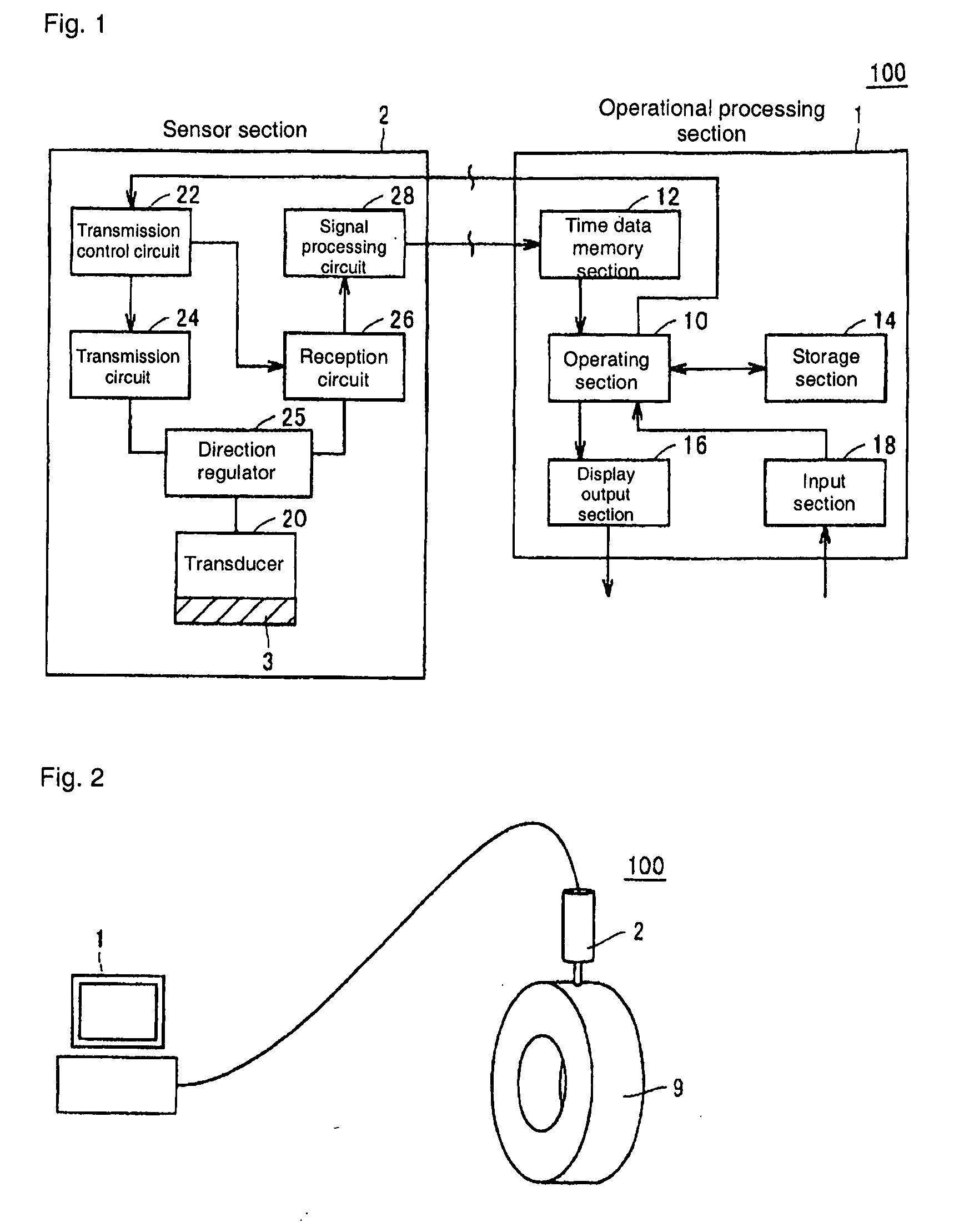
[0068]FIG. 1 shows a schematic constitutional view of a frictional characteristic measuring apparatus 100 according to Embodiment 1 of the present invention.

[0069] With reference to FIG. 1, the frictional characteristic measuring apparatus 100 is comprised of an operational processing section 1 and a sensor section 2. Further, in the frictional characteristic measuring apparatus 100, a sound wave that vibrates the object to be measured is emitted as an incident sound wave from the sensor section 2, and a reflected sound wave generated by reflection of the sound wave on the object to be measured is received by the sensor section 2. Moreover, in the frictional characteristic measuring apparatus 100, the operational processing section 1 calculates a frictional characteristic of the object to be measured based upon the reflected sound wave received by the sensor section 2. It should be noted that the incident sound wave emitted by the sensor section 2 is preferably an ultrasound wave. ...

embodiment 2

[0182] In Embodiment 1 above, the configuration was described where the sensor section and the operational processing section are connected to each other through a cable. In Embodiment 2, a configuration is described where the sensor section and operational processing section are connected with each other through a wireless signal.

[0183]FIG. 10 shows a schematic constitutional view of a frictional characteristic measuring apparatus 200 according to Embodiment 2. With reference to FIG. 10, the frictional characteristic measuring apparatus 200 is comprised of an operational processing section 4 and a sensor section 5.

[0184] The operational processing section 4 is comprised of a transmitting section 32, an operating section 30, the display output section 16, the storage section 14 and the input section 18.

[0185] Upon receipt of a measurement command through the input section 18, the operating section 30 gives an emission command to the transmitting section 32, and also receives time...

embodiment 3

[0228] In Embodiments 1 and 2 above, the configurations (front face reflection method) were described where the loss tangent is measured based upon the reflected sound wave generated by reflection on the surface of the object to be measured. In Embodiment 3 a configuration is described (bottom face reflection method) where a loss tangent is measured based upon two reflected sound waves generated by reflection on the flat face and the bottom face of the object to be measured.

[0229]FIG. 16 shows a schematic constitutional view of a frictional characteristic measuring apparatus 300 according to Embodiment 3.

[0230] With reference to FIG. 16, the frictional characteristic measuring apparatus 300 is comprised of an operational processing section 71 and a sensor section 72.

[0231] The operational processing section 71 is configured by replacing the operating section 10 with an operating section 70 in the operational processing section 1 of the frictional characteristic measuring apparatu...


PUM

PropertyMeasurementUnit
frequencyaaaaaaaaaa
frictional coefficientaaaaaaaaaa
viscoelasticaaaaaaaaaa

Abstract

In a frictional characteristic measuring apparatus, a sensor section emits a sound wave, which gives vibration to an object to be measured, as an incident sound wave, and receives a reflected sound wave generated by reflection of the sound wave on the object to be measured. An operational processing section derives a loss tangent of a viscoelastic characteristic of the object to be measured based upon the reflected sound wave received by the sensor section. Further, the operational processing section calculates a frictional characteristic from the derived loss tangent by means of a prescribed conversion constant. Moreover, the operational processing section previously emits an incident sound wave in a state where the object to be measured is not present, and stores the reflected sound wave as a reference value.

Description

BACKGROUND OF THE INVENTION [0001] 1. Field of the Invention [0002] The present invention relates to a frictional characteristic measuring apparatus for measuring a frictional characteristic of an object, and particularly relates to a frictional characteristic measuring apparatus capable of estimating a change in a frictional characteristic of a viscoelastic body condition. The invention also relates to a tire incorporating the frictional characteristic measuring apparatus. [0003] 2. Description of the Related Art [0004] Performance of a rubber product used for a tire, a roller and the like is determined according to a frictional characteristic thereof. For example, as for a tire, a so-called grip characteristic is acquired by frictional force generated between the tire and a road surface. Therefore, measurement of a frictional characteristic is important for evaluating a characteristic of the rubber product or the like in a product pre-shipment test, a test of deterioration in a pr...

Claims


Application Information

Patent Timeline
Patent Type & Authority Applications(United States)
IPC IPC(8): G01N29/04G01N29/11G01M17/02G01N19/02
CPCG01N29/11G01N29/2468G01N2291/045G01N2291/02836G01N2291/0423G01N2291/0258
Inventor OMATA, NOBUAKISUGA, TAKAHIROURABE, SHINICHI
Owner ORMON CORP
Why Eureka
Try Eureka