Spring energized lip seal faucet ball valve

Inactive Publication Date: 2007-02-22
MASCO CORP
View PDF26 Cites 4 Cited by
  • Summary
  • Abstract
  • Description
  • Claims
  • Application Information

AI Technical Summary

Benefits of technology

[0008] The ball valve assembly of this invention includes a positive location within a cavity that is provided by a non-sealing cam surface of the cam. An upper seal is disposed and supported with the cam and is in sealing contact with the ball valve in an area that is not in direct contact with the cam surface. In this way, the ball valve positioning function is separated from the sealing function. The separation of the sealing and location functions provide for the increased durability of the seal.
[0009] Accordingly, the faucet assembly of this invention provides a positive feel to the ball valve for the entire operational life of the ball valve without requiring replacement or seal adjustment.

Problems solved by technology

The elastomeric seals often would wear resulting in undesirable movement of the ball valve.

Method used


Image

  • Spring energized lip seal faucet ball valve
  • Spring energized lip seal faucet ball valve
  • Spring energized lip seal faucet ball valve

Examples


Embodiment Construction

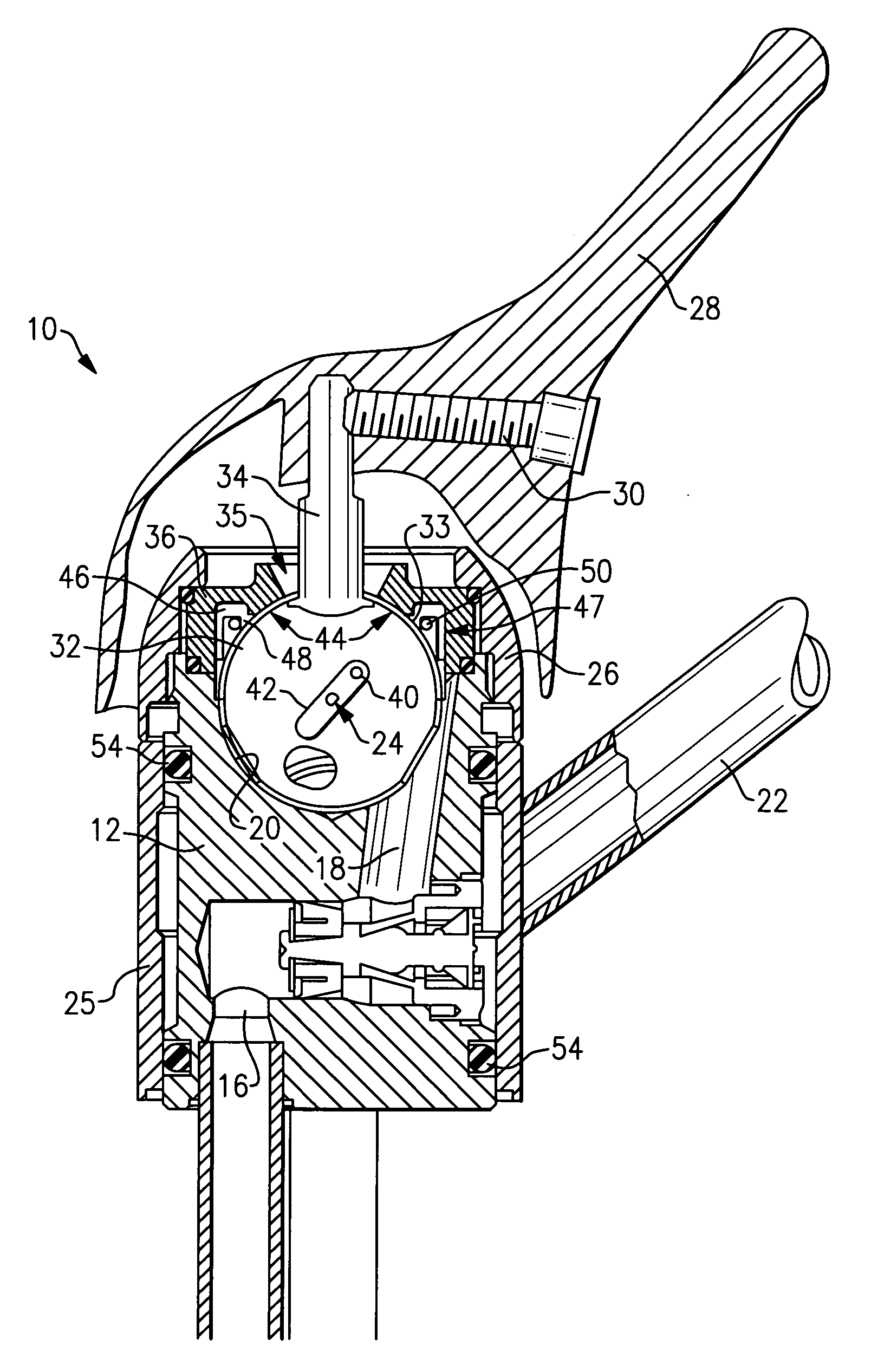
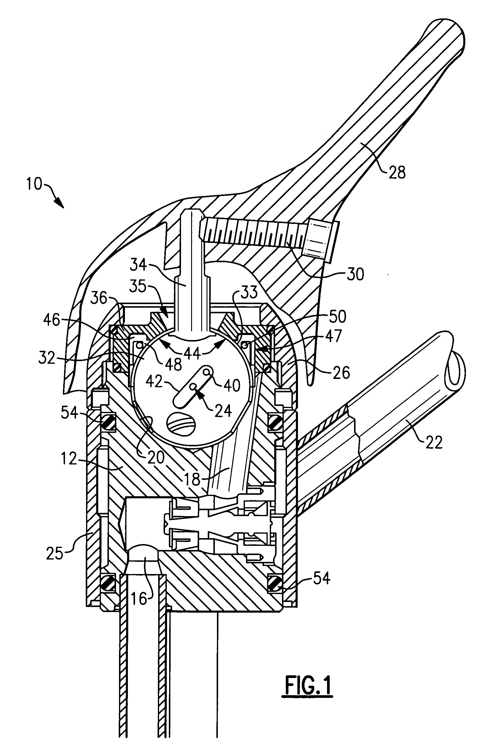
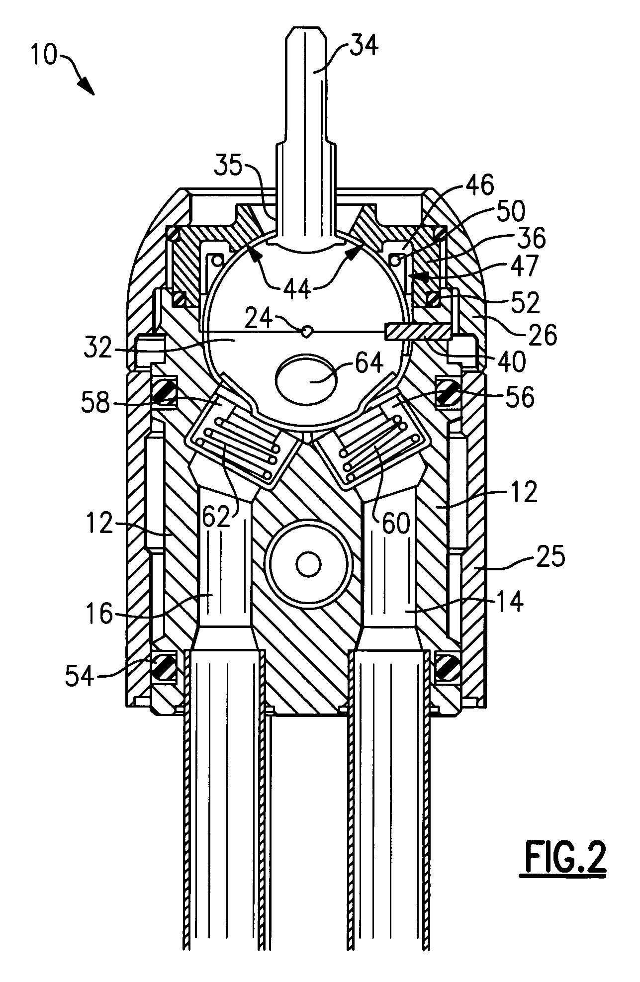
[0014] Referring to FIG. 1, the faucet assembly 10 includes a housing 12 that defines a first inlet 14 and a second inlet 16 (Best shown in FIG. 2). The housing 12 also defines an outlet 18 that provides a fluid passage to a spout 22. The housing 12 defines a cavity 20 that is in complete communication with the first and second inlets 14 and 16 and the outlet 18. The cavity 20 supports a ball valve 32 that includes inlet openings and outlet openings that corresponds to the inlets 14, 16 and outlet 18 that are defined within the housing 12. Spherical movement of the ball valve 32 about a point 24 selectively communicates fluid between the inlets 14, 16 and the outlet 18.

[0015] The ball valve 32 is held within the cavity 20 by a cam 36. The cam 36 positively locates and holds the ball valve 32 within the cavity 20. The cam 36 is held within the housing 12 by a cap 26. A cover 25 is assembled over the housing 12. O-rings 54 are disposed between the cover 25 and the housing 12. The O-r...


PUM


Abstract

A faucet assembly includes a housing that defines a cavity. Within the cavity there is a ball valve that is held in place by cam surfaces of a cam. The cam surfaces positively and directly contact the ball valve without a pliable seal member disposed there between. The possible location of the ball valve eliminates linear movement. Further, a seal assembly is disposed between the cam and the ball valve in locations that are not in direct contact with the cam surfaces. The cam surfaces hold the ball valve in place separately from the seal resulting in less load on the seal to provide lengthened seal life.

Description

BACKGROUND OF THE INVENTION [0001] This invention generally relates to a ball valve for a faucet. More particularly this invention relates to mounting of a ball valve assembly within a faucet. [0002] Faucet assemblies are known that include a ball valve for selectively controlling flow from a hot water and a cold-water inlet. The ball valve is typically disposed within a cavity defined by a faucet housing. The ball valve includes a stem that is manipulated to control the mixture of hot and cold water. The stem extends upward through a seal that prevents leakage along the stem of the ball valve. The inlets for the hot and cold water include seals that are biased against the ball valve. The ball valve is supported within the housing by a top seal disposed around the stem, and bottom seals for each of the inlets. Support of the ball valve assembly between the pliable top and bottom seals results in an undesirable spongy feel to the ball valve during operation. [0003] Disadvantageously,...

Claims


Application Information

Patent Timeline
IPC IPC(8): F16K11/076
CPCF16K11/087Y10T137/86823
Inventor PINETTE, THOMAS
Owner MASCO CORP
Why Eureka
Try Eureka