
Welding wire feeder and connection apparatus

a feeder and connection technology, applied in the field of arc welding technology, can solve the problems of increasing the impedance of the cable to switch contact connection, and achieve the effect of increasing the impedan

Inactive Publication Date: 2007-02-22
LINCOLN GLOBAL INC
View PDF5 Cites 30 Cited by
  • Summary
  • Abstract
  • Description
  • Claims
  • Application Information

AI Technical Summary

Benefits of technology

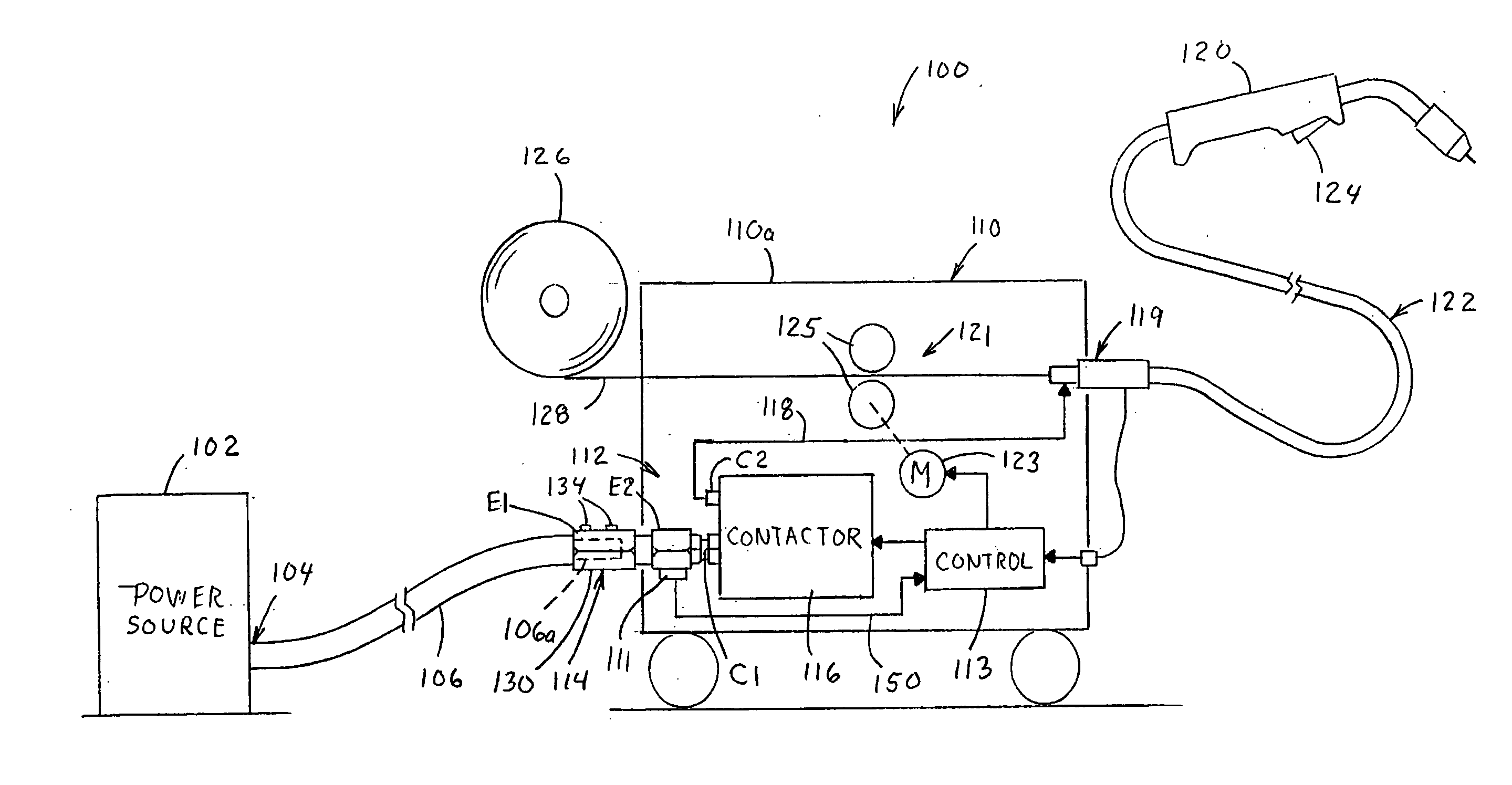
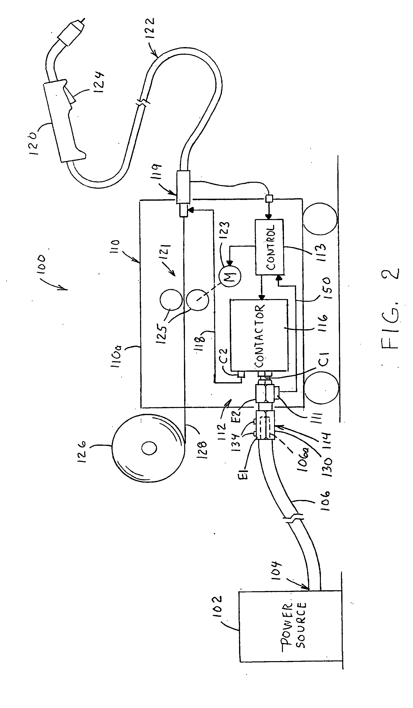
[0011] In another aspect of the invention, the input may further include a thermal sensor such as a thermocouple, thermostat, RTD, etc., mounted on the input connector. A control circuit may also be provided, which is coupled to the thermal sensor, the switching device, and the output in the wire feeder, where the control circuit controls the operating condition of the switching device according to a temperature signal from the thermal sensor and according to a trigger signal from a torch connected to the output. In one example described below, the control circuit places the switching device in the first operating condition when the torch trigger is actuated by the operator and the temperature signal indicates that the connector is below a predetermined threshold temperature. However, when the connector temperature rises above the threshold temperature (or when the trigger is off), the control circuit puts the contactor in the second operating condition. In this manner, the thermal device signals the controller inside the wire feeder indicating the connector has exceeded a safe operating temperature, such as through loose or intermittent power connection causing increased impedance in the cable to switch contact connection. The controller can accordingly shut down the wire feeder, and may also alert the operator of the problem so it can be fixed before major damage occurs.

Problems solved by technology

In this manner, the thermal device signals the controller inside the wire feeder indicating the connector has exceeded a safe operating temperature, such as through loose or intermittent power connection causing increased impedance in the cable to switch contact connection.

Method used


Image

  • Welding wire feeder and connection apparatus
  • Welding wire feeder and connection apparatus
  • Welding wire feeder and connection apparatus

Examples


Embodiment Construction

[0023] The invention relates to portable welding wire feeders with reliable and easily serviceable input connections for power source cables. One or more exemplary implementations of the present invention are hereinafter illustrated and described, wherein like reference numerals are used to refer to like elements throughout and wherein the illustrated structures are not necessarily drawn to scale.

[0024] Referring initially to FIGS. 2 and 3, various aspects of the invention are illustrated in conjunction with a welder or welding system 100 including a power source 102, a portable wire feeder 110 and a welding torch 120 coupled to the wire feeder 110 by a torch cable 122. The power source 102 converts input power to provide welding current and voltage waveforms (e.g., a welding signal) at an electrical output 104 thereof for selective application of the welding signal to a welding process (not shown) via a circuit formed by a power source cable 106, a wire feeder input 112 with an in...


PUM

PropertyMeasurementUnit
electrical poweraaaaaaaaaa
conductiveaaaaaaaaaa
temperatureaaaaaaaaaa

Abstract

Welding wire feeders are disclosed for providing welding wire and electrical power to a welding torch in a welding system, in which an input is provided including an input connector integrated into a switching device of the wire feeder or coupled thereto directly or through a short cable. The input connector includes a cavity to receive wire from a power source cable with a clamping device being provided for selectively clamping the cable wire to the connector or releasing the wire therefrom using only simple tools.

Description

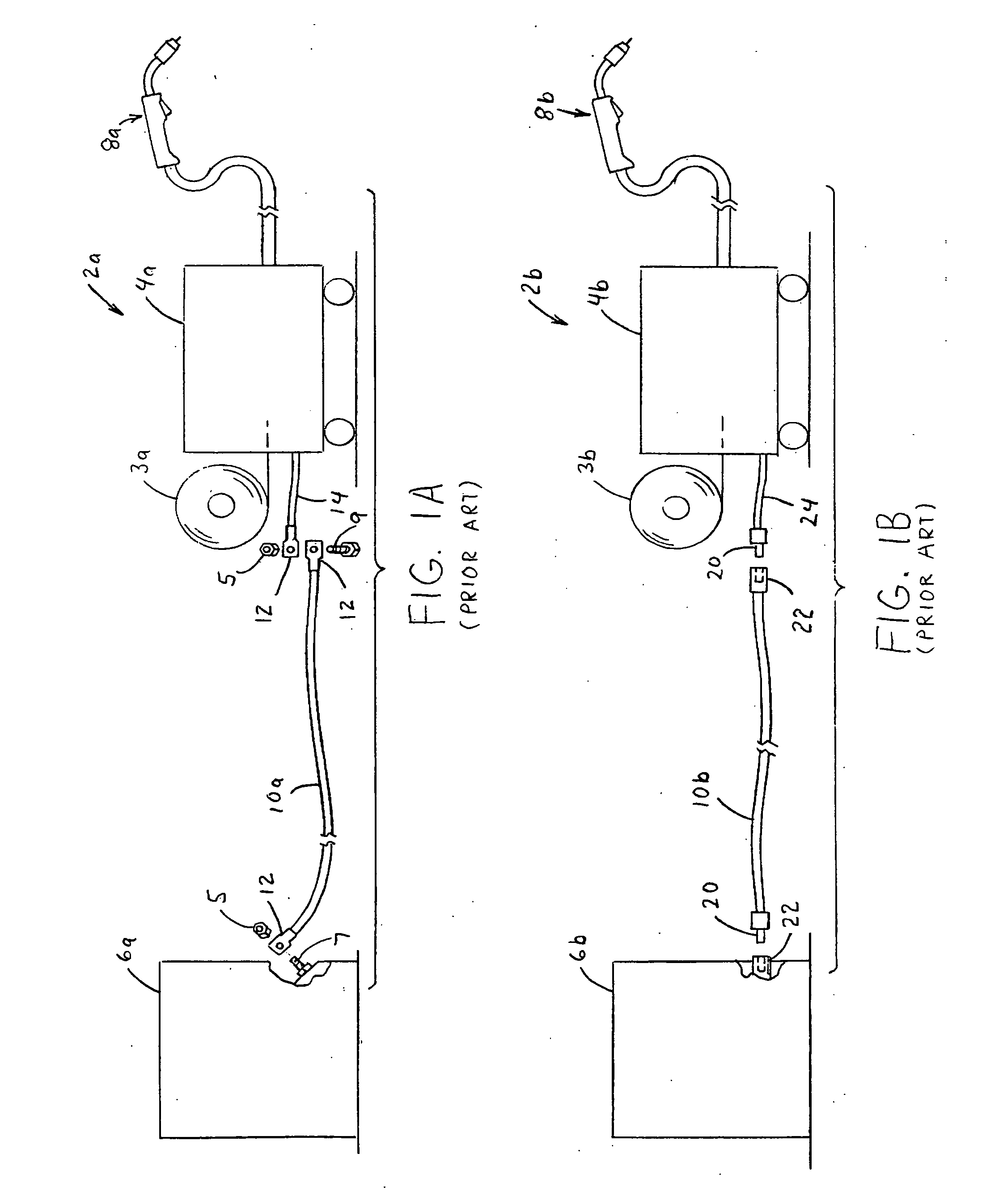
FIELD OF THE INVENTION [0001] The present invention relates generally to arc welding technology, and more particularly to portable welding wire feeders and apparatus for connecting a welding power cable thereto. INCORPORATION BY REFERENCE [0002] Portable welding wire feeders and related technology is generally set forth in the following Unite State patents, the contents of which are hereby incorporated by reference as background information: Bellefleur U.S. Pat. No. 4,665,300; Kroll U.S. Pat. No. 4,508,954; Chandler U.S. Pat. No. 6,225,596; Miller U.S. Pat. No. 5,410,126; Grimm U.S. Pat. No. 5,836,539; and Matiash U.S. Pat. No. 6,707,004. BACKGROUND OF THE INVENTION [0003] Welding operations generally involve providing a welding arc between a welding electrode and a workpiece being welded, where the arc operates to melt the electrode material for deposition onto the workpiece to create a weld joint. Modem welding systems include a power source and a wire feeder, as well as a supply ...

Claims


Application Information

Patent Timeline
Patent Type & Authority Applications(United States)
IPC IPC(8): B23K9/10
CPCB23K9/1336
Inventor ENYEDY, EDWARD A.JUSTICE, KENNETH L.
Owner LINCOLN GLOBAL INC
Learn More