Optical tactile sensor and method of reconstructing force vector distribution using the sensor

a technology of optical tactile sensors and force vector distribution, which is applied in the direction of instruments, force measurement by measuring optical property variation, force/torque/work measurement apparatus, etc., can solve the problems of difficult reconstruction of force vector distribution with arbitrary curved surfaces, inability to acquire force vector distribution by optical tactile sensors, and difficulty in resolving force vector distribution. , to achieve the effect of convenient processing

Inactive Publication Date: 2007-02-22
TOUDAITLO LTD
View PDF4 Cites 47 Cited by
  • Summary
  • Abstract
  • Description
  • Claims
  • Application Information

AI Technical Summary

Benefits of technology

[0020] In one preferred aspect, the imaging device is arranged at a position opposite to the side of the transparent elastic body contacted by the object. Also, in the case where there exists a plurality of colored markers having different colors from each other, it is desirable to carry out convenient processing after imaging by selecting only markers of a particular color and looking at them separately. Selection of a particular color marker is carried out by, for example, using a color filter. It is desirably to provide a light shielding layer on the sensing surface to stabilize an image of markers.

Problems solved by technology

However, it is difficult to reconstruct the force vector distribution from the strain information because an amount of information is insufficient.
However, it is difficult to reconstruct force vector distribution with an arbitrary curved surface.
However, it is not possible to acquire force vector distribution by this sensor.

Method used


Image

  • Optical tactile sensor and method of reconstructing force vector distribution using the sensor
  • Optical tactile sensor and method of reconstructing force vector distribution using the sensor
  • Optical tactile sensor and method of reconstructing force vector distribution using the sensor

Examples


Embodiment Construction

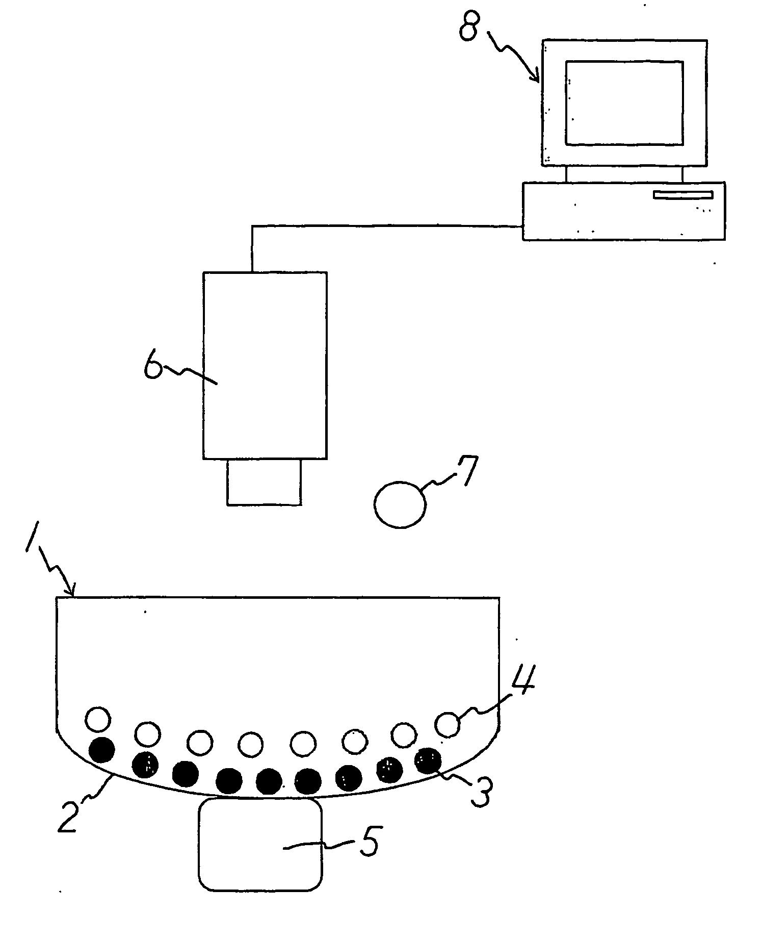
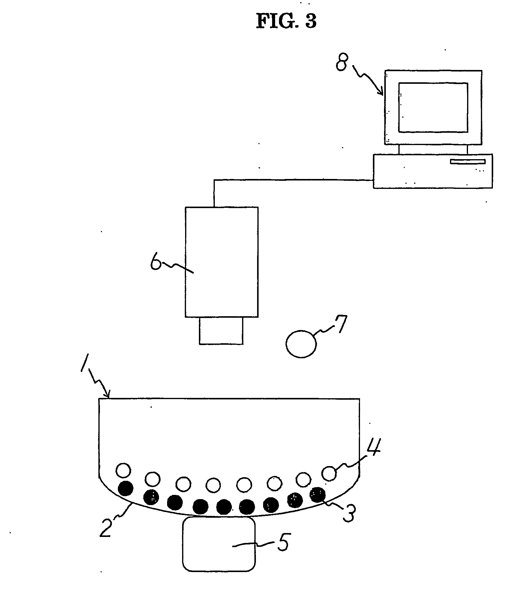
[0035] Referring to FIG. 3, the construction of an optical tactile sensor of the present invention is shown. The sensor comprises a transparent elastic body 1 formed of a transparent elastic material and a curved surface 2, or a surface for sensing. The transparent elastic body 1 is provided with a plurality of colored markers 3, 4 embedded in the transparent elastic body 1 in the vicinity of the surface 2 and along the curved surface 2. A sensing section is comprised of the transparent elastic body 1 and the colored markers 3, 4 arranged inside the elastic body.

[0036] The colored markers 3, 4 are comprised of two groups of colored markers and the two marker groups are embedded in different depths respectively from the surface 2. Colored markers 3 constituting one marker group and colored markers 4 constituting the other marker group have different colors to each other. For example, one marker group consists of a plurality of blue markers 3 and the other marker group consists of a ...


PUM

PropertyMeasurementUnit
forceaaaaaaaaaa
radiusaaaaaaaaaa
depthaaaaaaaaaa

Abstract

The invention relates to a tactile sensor capable of obtaining information for a plurality of degrees of freedom at each point on a surface. An optical tactile sensor is provided with a sensing part and a photographing device, the sensing part comprising a transparent elastic body and a plurality of groups of markers provided inside the elastic body, each marker group being made up of a number of colored markers, with markers making up different marker groups having different colors for each group. The elastic body has an arbitrary curved surface. The behavior of the colored markers when an object touches the curved surface of the elastic body is obtained as image information of markers by photographing device. The sensor further comprises a force vector distribution reconstructing device for reconstructing forces applied to said surface from information as to the behavior of markers that is obtained from said image information of markers.

Description

FIELD OF THE INVENTION [0001] The present invention relates to an optical tactile sensor, and preferably to a tactile sensor used for a robot hand. BACKGROUND OF THE INVENTION [0002] When considering understanding the contact state of a contact surface using a tactile sensor, there are vectors of three components representing magnitude and direction of force acting at each point of the contact surface. This is represented as f(x,y) in the coordinate system of FIG. 1. Here, f is a vector, and so actually has three components x, y and z at each point. When explicitly expressing each component, it is represented as f(x,y)=[fx(x,y), fy(x,y), fz(x,y)]. [0003] Some of inventors of the present invention et al. have proposed an optical tactile sensor that is capable of measuring three-dimensional force vector distribution. The optical tactile sensor is disclosed in WO02 / 188923 A1 and incorporated herein by reference. A principle of the optical tactile sensor will be explained based on FIG. ...

Claims


Application Information

Patent Timeline
Patent Type & Authority Applications(United States)
IPC IPC(8): G06M7/00B25J13/08G01L1/04G01L1/24G01L5/16G01L5/22
CPCB25J13/084G01L5/228G01L5/166G01L1/24
Inventor MIZOTA, TERUKAZUKAMIYAMA, KAZUTOKAJIMOTO, HIROYUKIKAWAKAMI, NAOKITACHI, SUSUMU
Owner TOUDAITLO LTD
Why Eureka
Try Eureka