
Volume rendering apparatus and process

a volume rendering and volume technology, applied in the field of volume rendering, can solve the problems of degrading the performance of the volume rendering application, the limitations of the gpus discussed above, and the weak performance of the gpus

Active Publication Date: 2007-02-22
TOSHIBA MEDICAL VISUALIZATION SYST EURO
View PDF20 Cites 40 Cited by
  • Summary
  • Abstract
  • Description
  • Claims
  • Application Information

AI Technical Summary

Benefits of technology

[0041] Another option for reuse is when, during arrangement of the rays into ray tiles, prior arrangements are reused when the prediction of the amount of processing needed to render each ray or ray segment is substantially the same for two or more ray blocks, for example the same or within a defined similarity range (e.g. ±1%, 5%, 10%). In this case the prediction of the amount of processing needed to render each ray or ray segment can be based on the configuration of sub-volumes that enclose the subset of the voxels that will have a significant effect on the rendering relative to the ray block concerned. The reusing can be implemented by reusing scatter maps and/or gather maps in this case also.
[0042] A further option for reuse i

Problems solved by technology

However, for a number of years, application software to implement volume rendering on standard personal computers (PCs) and workstations is well known which does not utilize any bespoke hardware.
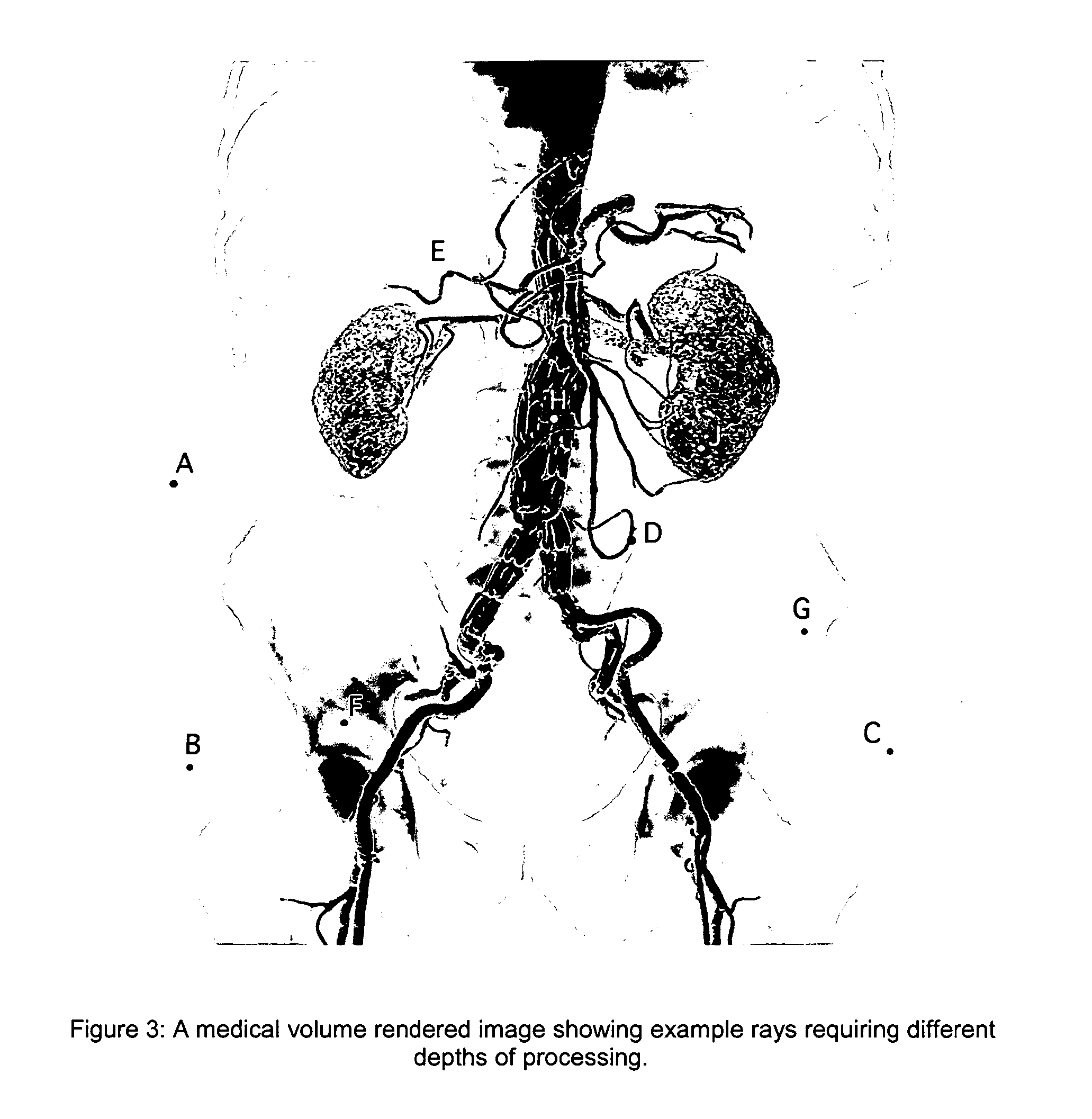
However, when applied to volume rendering in medicine, the SIMD limitations of GPUs discussed above will tend to have a strong detrimental effect on performance for the following reasons: Although CT, MR, and PET scanners scan a large section of the body, the typical display requirement is to show only certain organs, such as blood vessels, kidneys, the skeleton, etc.
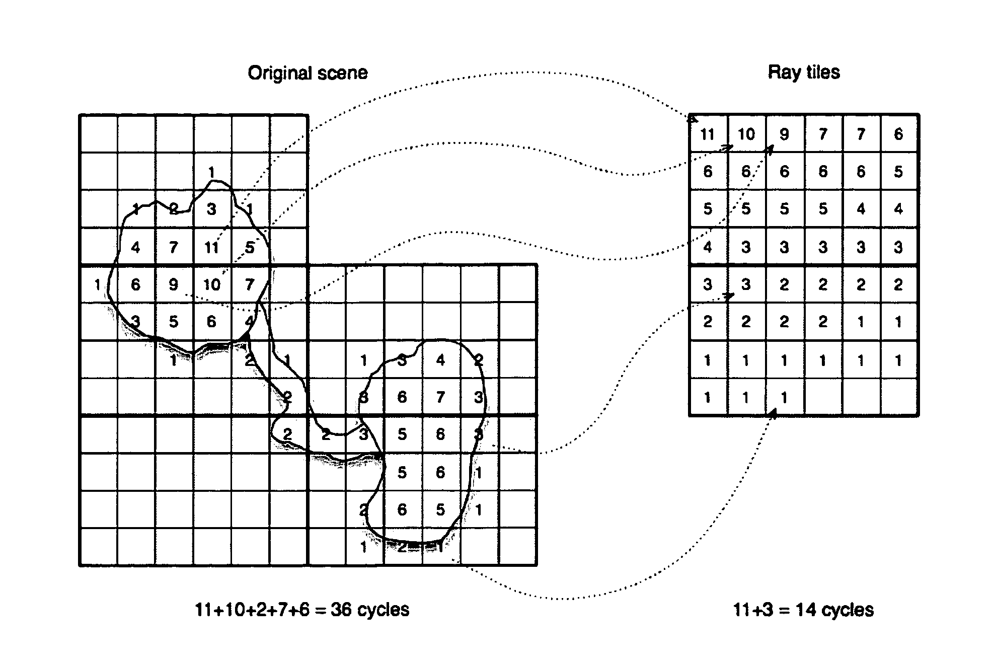
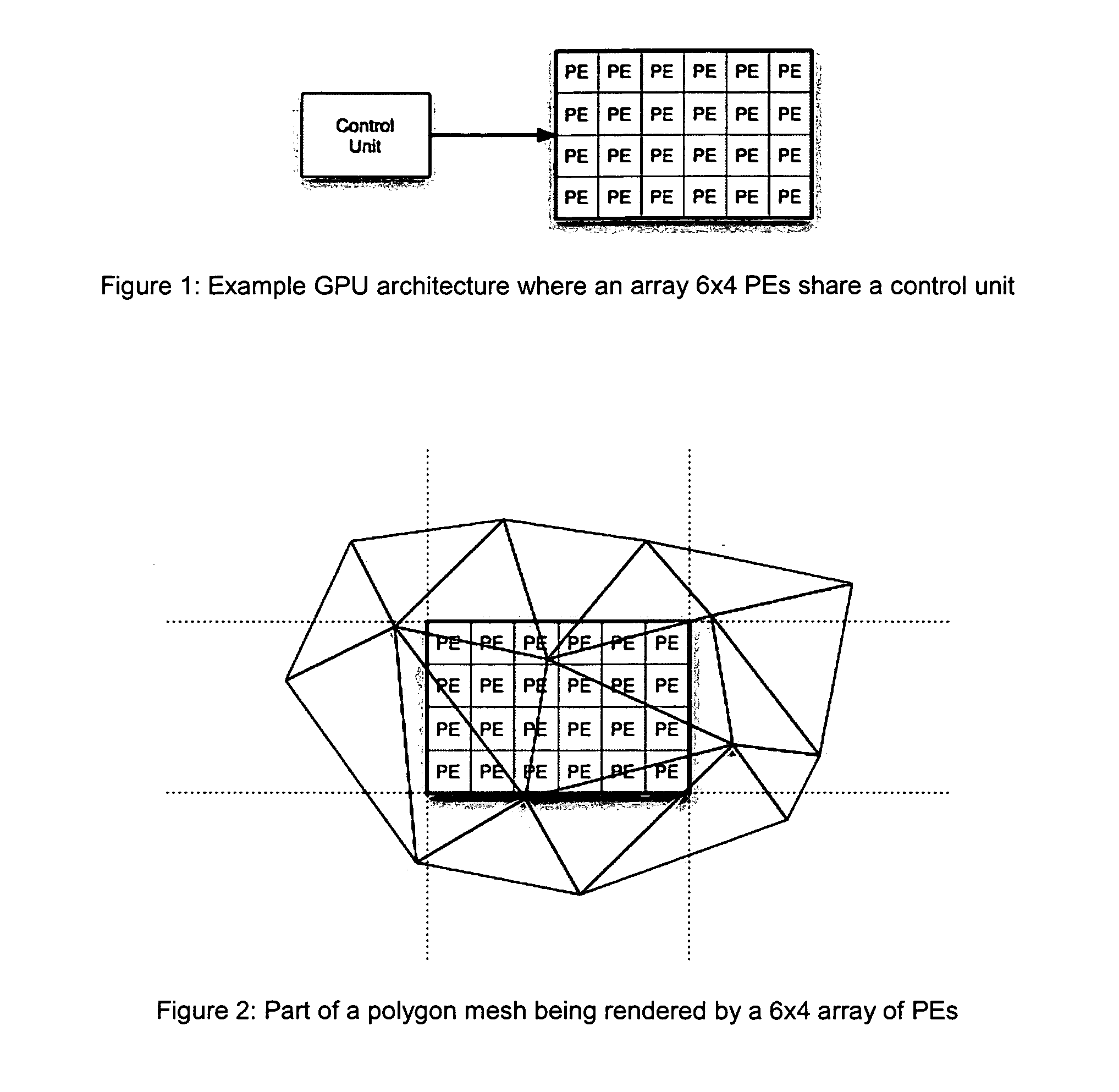
The SIMD limitations means that the overall processing time of a tile of pixels, such as the 6×4 tile described in the example, is the time needed to process the longest ray in the tile.
However, a similar variability of the depth of rays that need to be processed occurs at the 6×4 or similar tile scale, and thus the SIMD limitations of the GPU degrade the performance of the volume rendering application.

Method used


Image

  • Volume rendering apparatus and process
  • Volume rendering apparatus and process
  • Volume rendering apparatus and process

Examples


example

[0119]FIG. 7 shows an example of volume rendering scene (simplified for illustration) where two ray blocks have the same internal configuration of sub-volumes. However, due to the arbitrary real-valued position of ray block projections within the rendered image, there is a fractional displacement of the ray grid with respect to each block. This means that, in principle, two separate scatter and gather maps need to be constructed. It is advantageous to overcome this issue and reuse the same scatter and gather maps.

[0120] In this situation, it is possible to re-use gather and scatter maps by considering each ray block in isolation and performing the gather operation into an intermediate image. First, each ray block is individually translated to an intermediate space, for example so that it lies as close as possible to the origin on the bottom right quadrant of the space. Then the ray block is rendered according to the present invention in that intermediate image space. It will be app...


PUM


Abstract

A computer automated process is presented for accelerating the rendering of sparse volume data on Graphics Processing Units (GPUs). GPUs are typically SIMD processors, and thus well suited to processing continuous data and not sparse data. The invention allows GPUs to process sparse data efficiently through the use of scatter-gather textures. The invention can be used to accelerate the rendering of sparse volume data in medical imaging or other fields.

Description

BACKGROUND OF THE INVENTION [0001] The invention relates to volume rendering, in particular how to provide acceleration of the volume rendering when using a computer system that includes a graphics processing unit (GPU). [0002] Volume rendering is a standard method of displaying 2D projections of the 3D data sets collected by medical imaging equipment, such as computer-assisted tomography (CT) scanners, magnetic resonance (MR) scanners, ultrasound scanners and positron-emission-tomography (PET) systems. In the early days of medical imaging, volume rendering was performed on vendor-specific software and hardware associated with the scanner. However, for a number of years, application software to implement volume rendering on standard personal computers (PCs) and workstations is well known which does not utilize any bespoke hardware. [0003] It is also the case that modern personal computers and workstations include a graphics card, and in most cases the graphics card includes a Graphi...

Claims


Application Information

Patent Timeline
IPC IPC(8): G06T17/00G06T15/08
CPCG06T15/08
Inventor PAPAGEORGIOU, PAVLOS
Owner TOSHIBA MEDICAL VISUALIZATION SYST EURO
Learn More