Backlight module and light guide plate therein and method for diminishing corner shadow area

a backlight module and light guide plate technology, applied in lighting and heating apparatus, lighting device details, instruments, etc., can solve the problems of limited improvement, difficult to increase the size or density of optical patterns on parts of the bottom surface, and limited improvemen

Inactive Publication Date: 2007-02-22
AU OPTRONICS CORP
View PDF7 Cites 11 Cited by
  • Summary
  • Abstract
  • Description
  • Claims
  • Application Information

AI Technical Summary

Benefits of technology

[0018] The present invention provides a fundamental method to solve the problem of the corner shadow area. The present invention utilizes the optical microstructure to change the propagating direction of the light. As a result, the quantity of light entering the corner shadow area is increased, so that the problem is solved fundamentally.

Problems solved by technology

However, the improvement is limited because the light passing through the corner shadow area 21 is quite a little.
However, it is difficult to increase the size or the density of the optical patterns on part of the bottom surface 204 by the v-cut technology.
However, as described above, because the light passing through the corner shadow areas 21 and 22 is quite a little, the improvement is limited.
Therefore, this prior art has its limitation.

Method used


Image

  • Backlight module and light guide plate therein and method for diminishing corner shadow area
  • Backlight module and light guide plate therein and method for diminishing corner shadow area
  • Backlight module and light guide plate therein and method for diminishing corner shadow area

Examples


Embodiment Construction

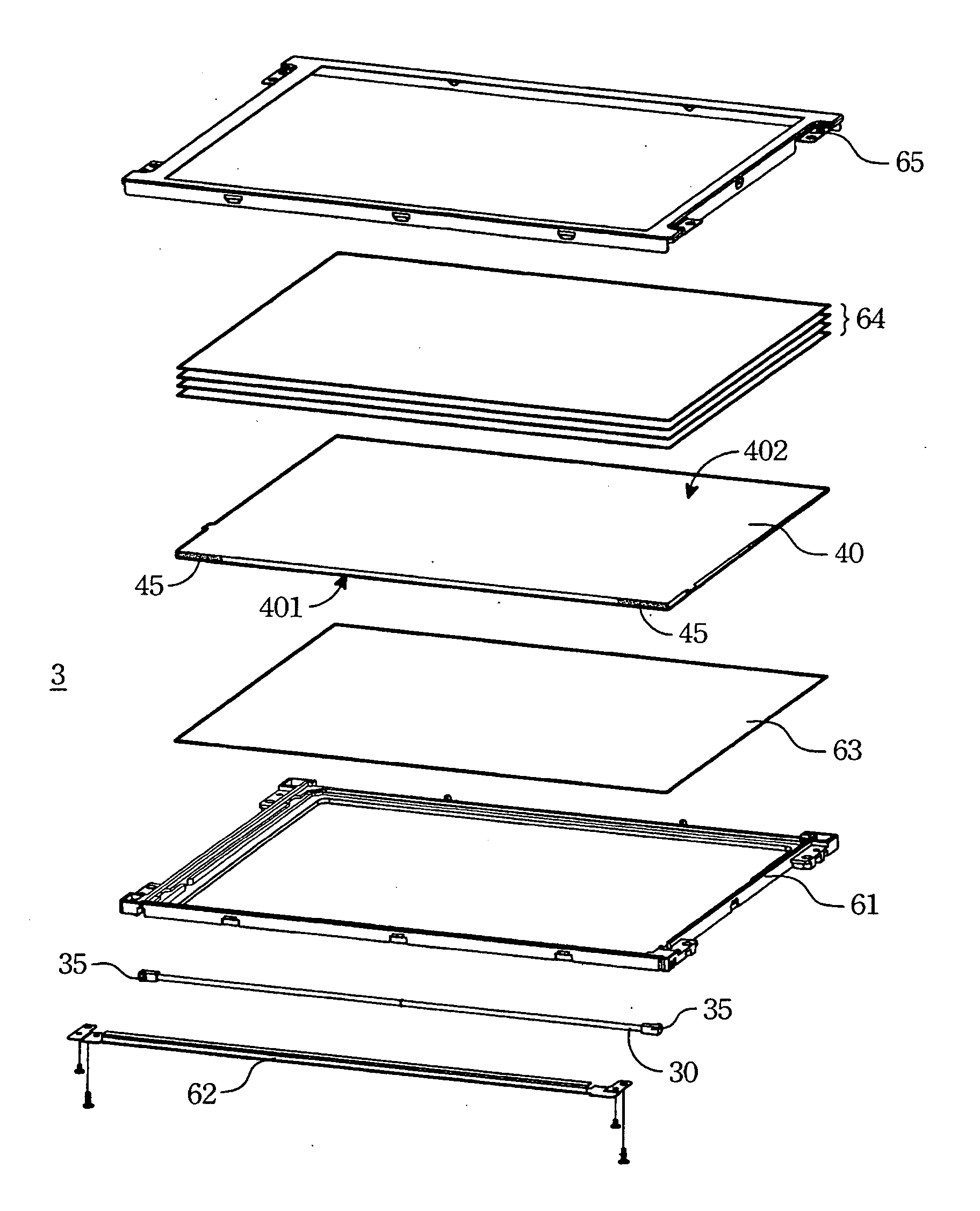
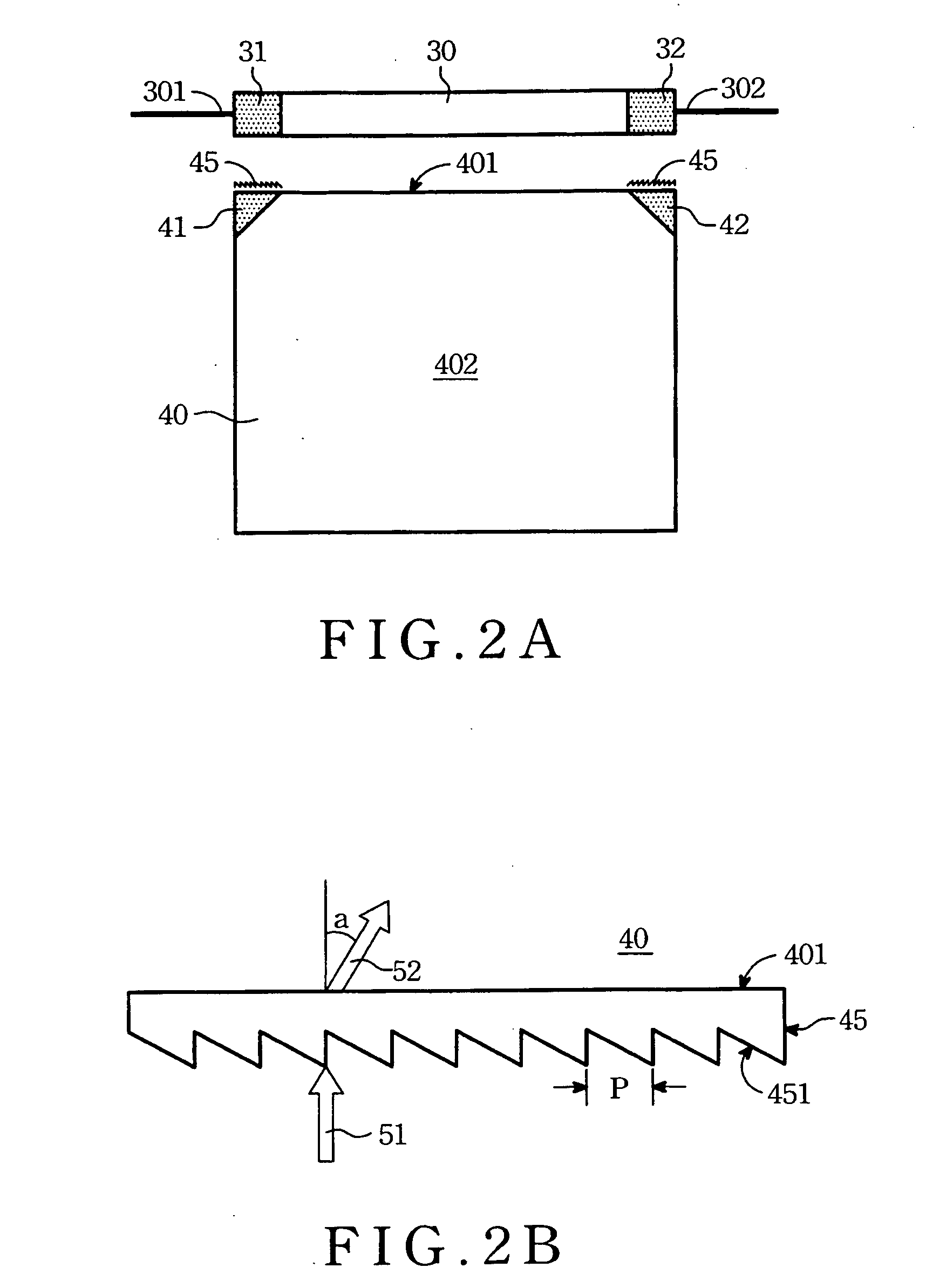
[0027] Please refer to FIG. 2A. FIG. 2A is a top view of a light guide plate and a lamp of a backlight module according to the present invention. The backlight module 3 includes a lamp 30 and a light guide plate 40. The light guide plate 40 has an edge side 401 and a light emitting surface 402. The lamp 30 is disposed on the edge side 401. Light generated by the lamp 30 diffuses inside the light guide plate 40 due to total internal reflection and emits out from the light guide plate 40 through the light emitting surface 402. The light is provided for a display panel (not shown in FIG. 2A).

[0028] The lamp 30 has two electrode ends 301 and 302. The lamp 30 of the embodiment shown in FIG. 2A is tube-shaped, and the electrode ends 301 and 302 are disposed respectively on two ends of the lamp 30. However, the lamp 30 can be shaped in any other form. Thus, the electrode ends 301 and 302 can be disposed on the same side of the lamp 30 as well. Due to the obstructing of the bushings of the...


PUM


Abstract

A backlight module is provided. The backlight module includes a light guide plate, a lamp and an optical microstructure. The light guide plate has an edge side. The lamp is disposed on the edge side of the light guide plate. The lamp has an electrode end. The light guide plate has a corner shadow area adjacent to the corner shadow area. Light generated by the lamp propagates toward the edge side in the first direction. The optical microstructure is disposed on a surface of the edge side of the light guide plate and guides the light toward the second direction to enter the corner shadow area.

Description

BACKGROUND OF THE INVENTION [0001] (1) Field of the Invention [0002] The present invention generally relates to an edge-type backlight module, a manufacturing method thereof and a light guide plate within the backlight module. [0003] (2) Description of the Prior Art [0004] A non-luminous display panel, such as a liquid crystal panel, usually needs a backlight source to display an image. In the prior art of the backlight sources, the edge-type backlight module meets the demand of thinning the products. [0005] Please refer to FIG. 1A and FIG. 1B. FIG. 1A and FIG. 1B illustrate a lamp 10 and a light guide plate 20 of a conventional backlight module. FIG. 1A is a top view of the lamp 10 and the light guide plate 20. FIG. 1B is a sectional side view of the lamp 10 and the light guide plate 20. The lamp 10 is disposed on an edge side 201 of the light guide plate 20 in the so-called edge-type backlight module. Light diffuses in the light guide plate 20 due to total internal reflection and ...

Claims


Application Information

Patent Timeline
Patent Type & Authority Applications(United States)
IPC IPC(8): F21V7/04
CPCG02B6/0036G02B6/0061G02B6/0081
Inventor KAO, KO-CHIALIAO, JING-HUANCHEN, CHIH-KUANGHUANG, JYH-HAUR
Owner AU OPTRONICS CORP
Why Eureka
Try Eureka