Image forming apparatus
- Summary
- Abstract
- Description
- Claims
- Application Information
AI Technical Summary
Benefits of technology
Problems solved by technology
Method used
Image

Examples
first embodiment
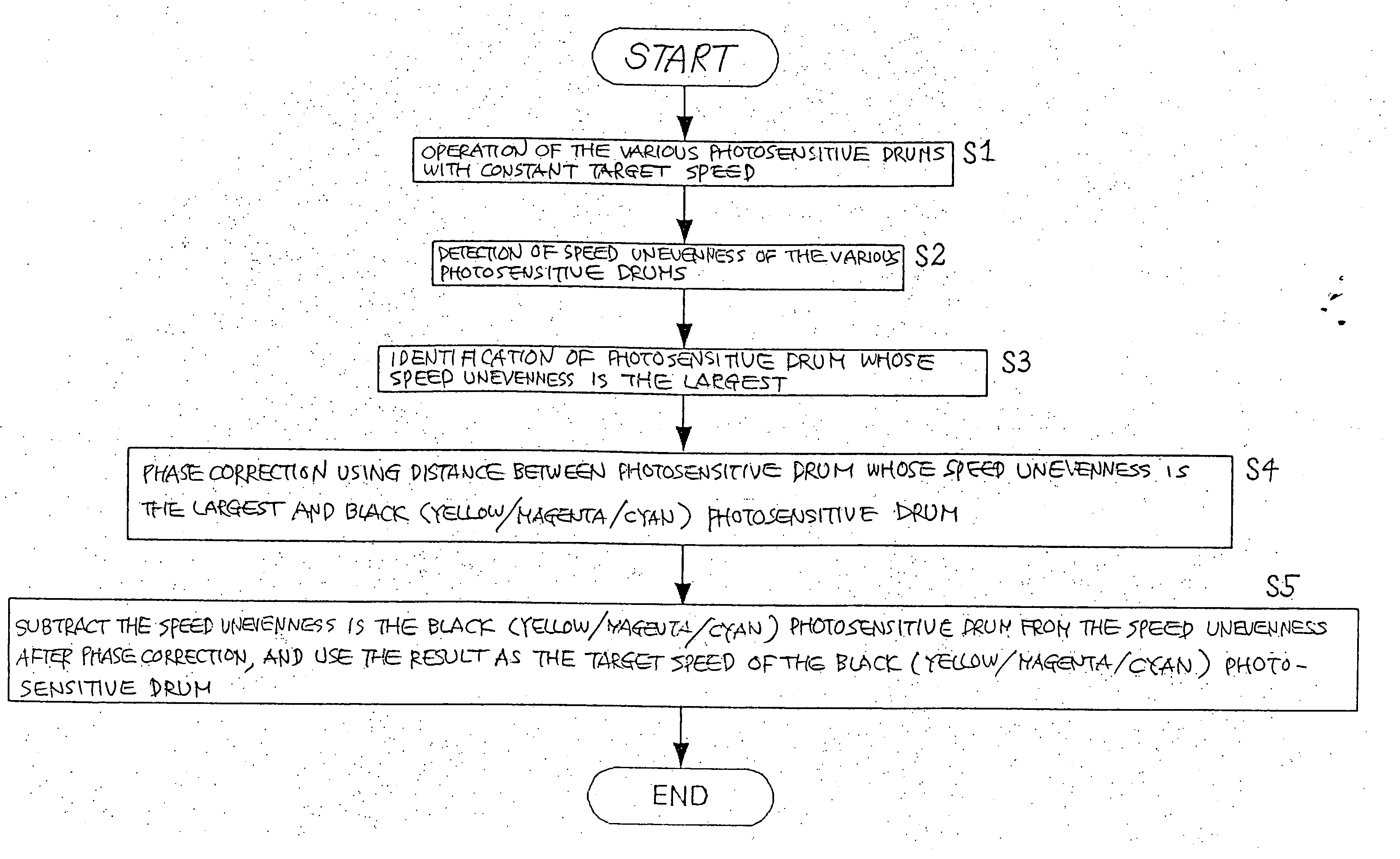
[0029] This embodiment consists in an image forming apparatus wherein phase correction is performed by detecting the rotational speed unevennesses of the photosensitive drums and finding phase correction values from the distances between the photosensitive drums, and exercising control such that the speeds of the other photosensitive drums are matched with the speed of the photosensitive drum that displays the largest speed unevenness.
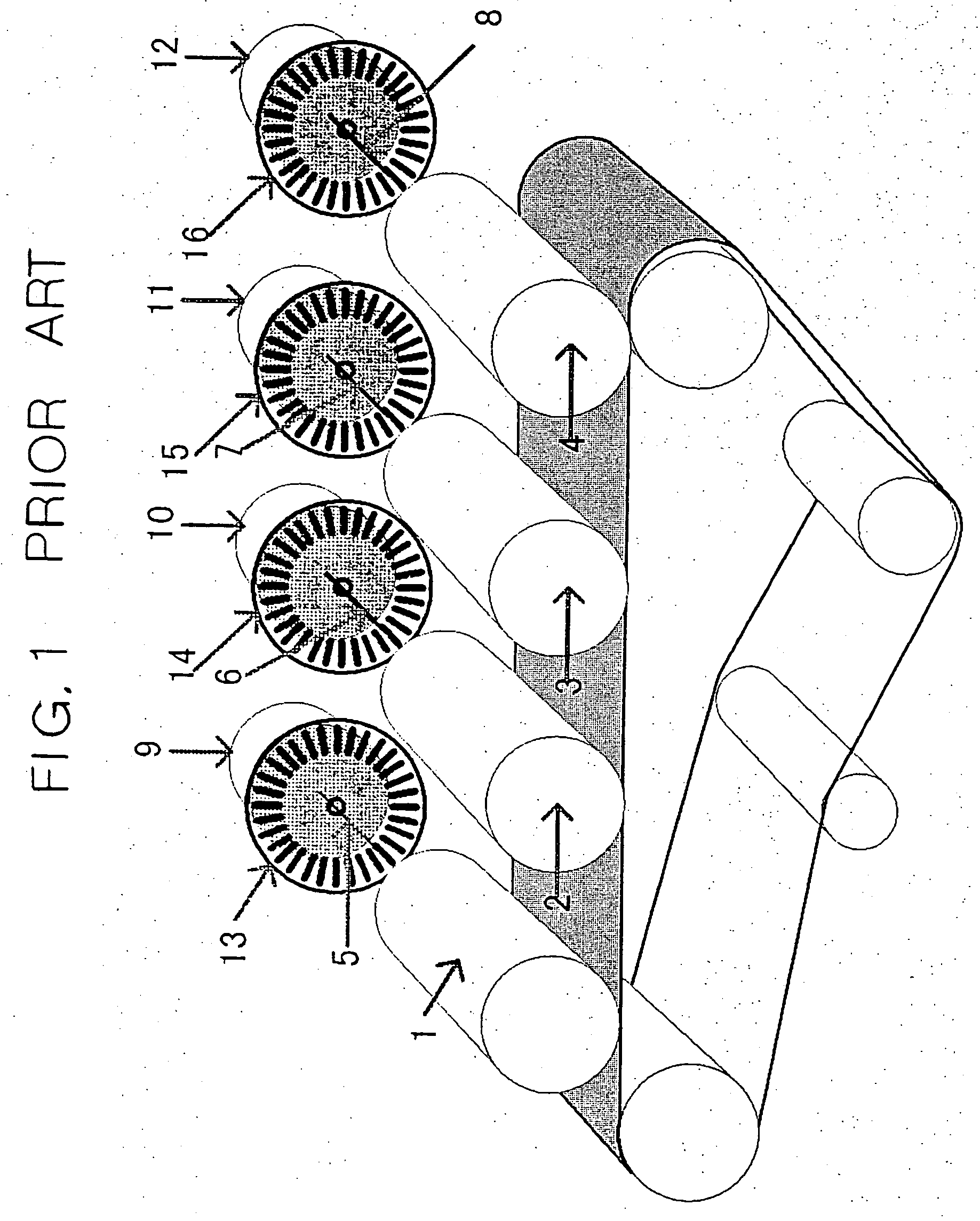
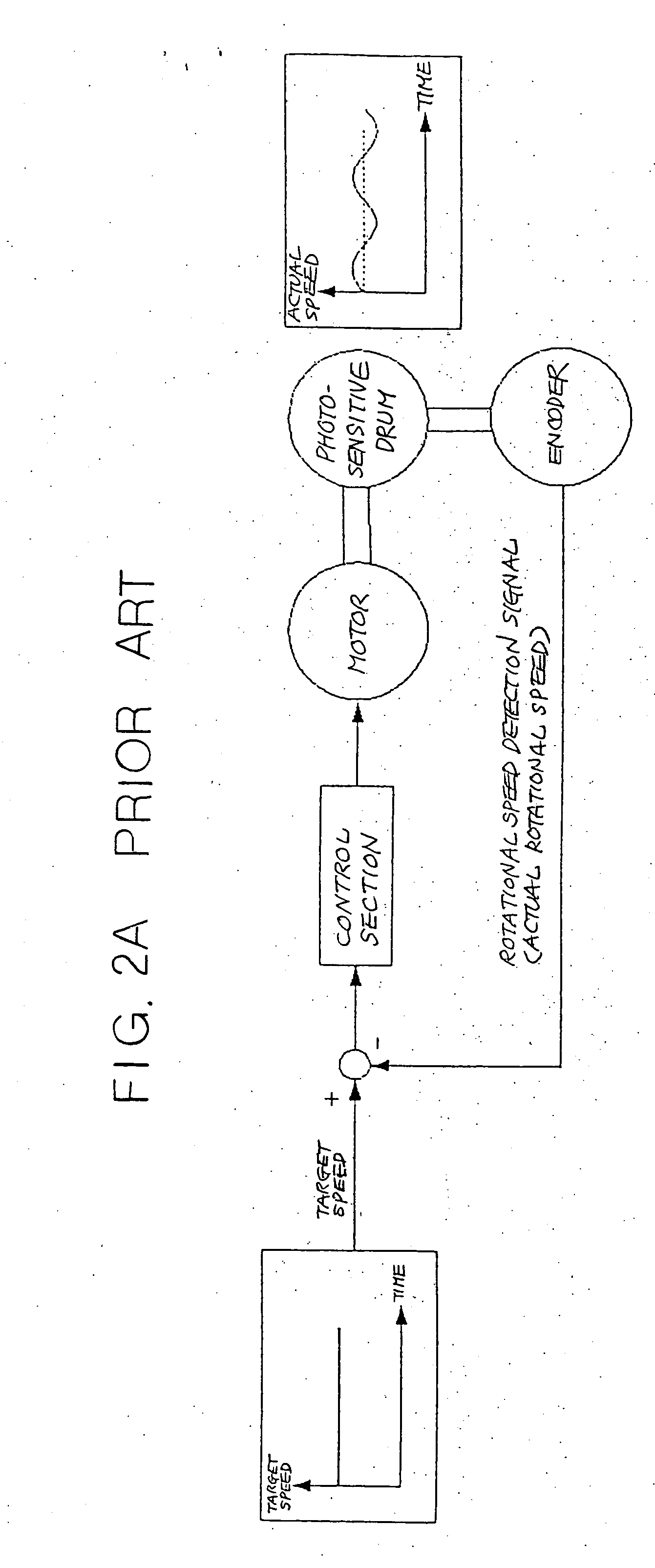
[0030] The basic construction of the image forming apparatus according to this embodiment is the same as that of the prior art. However, the section that controls rotational speed unevenness of a photosensitive drum differs from that of the prior art. FIG. 4 to 7 show the diagrammatic construction of a photosensitive drum drive system of an image forming apparatus according to this embodiment; FIG. 8 shows a method of calculating a phase correction; and. FIG. 9 shows a flow chart showing a phase correction sequence, respectively.
[0031] Next, the func...
second embodiment
[0038] This embodiment provides an image forming apparatus wherein a test image is output by detecting the rotational speed unevenness of the various photosensitive drums and exercising control such that the speed of the other photosensitive drums is matched with the speed of the photosensitive drum of largest speed unevenness; a phase correction is performed by finding a phase correction value from this test image, and control is again exercised such that the speed of the other photosensitive drums is matched with the speed of the photosensitive drum of largest speed unevenness.
[0039] The basic construction of the image forming apparatus according to this embodiment is the same as that of the above first embodiment. However, the section that finds the phase correction value of the photosensitive drums differs from that of the first embodiment. FIG. 10 is an operational flow chart of the phase correction means of the image forming apparatus according to this embodiment. FIG. 11 is ...
PUM
 Abstract
Description
Claims
Application Information