Microfluidic laminar flow detection strip

a technology of microfluidic laminar flow and detection strip, which is applied in the field of microfluidic devices, can solve the problems of low detection cost and simple assay complexity, the application of such assays to nucleic acid detection has yet to be fully developed, and the sensitivity of such assays is often questioned

Inactive Publication Date: 2007-02-22
PERKINELMER HEALTH SCIENCES INC
View PDF30 Cites 140 Cited by
  • Summary
  • Abstract
  • Description
  • Claims
  • Application Information

AI Technical Summary

Benefits of technology

[0023] In a second embodiment, a method of using the foregoing microfluidic laminar flow detection strip devices to detect the presence of an analyte of interest in a liquid sample is provided that comprises: (a) introducing the liquid sample into the first inlet of the device; (b) depressing the bellows pump; (c) releasing the bellows pump to draw the liquid sample through the microfluidic channel; and (d) visually inspecting the first bound antibody zone and the control zone for any color changes.
[0024] In a more specific embodiment of the foregoing met

Problems solved by technology

However, such environments require that the detection methods be of low cost and simple assay complexity.
Although lateral flow assays have been developed extensively for detection of antigens or antibodies, the application of such assays to nucleic acid detection has yet to be fully developed.
Most importantly, the sensitivity of such assays has often been questioned due to various limitations associated with the currently available formats (see, e.g., Giles et al., Journal of Medical Virology 59:104

Method used


Image

  • Microfluidic laminar flow detection strip
  • Microfluidic laminar flow detection strip
  • Microfluidic laminar flow detection strip

Examples


first embodiment

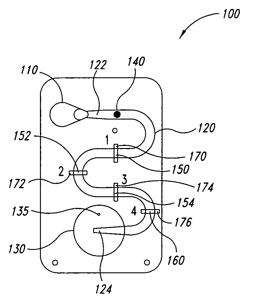
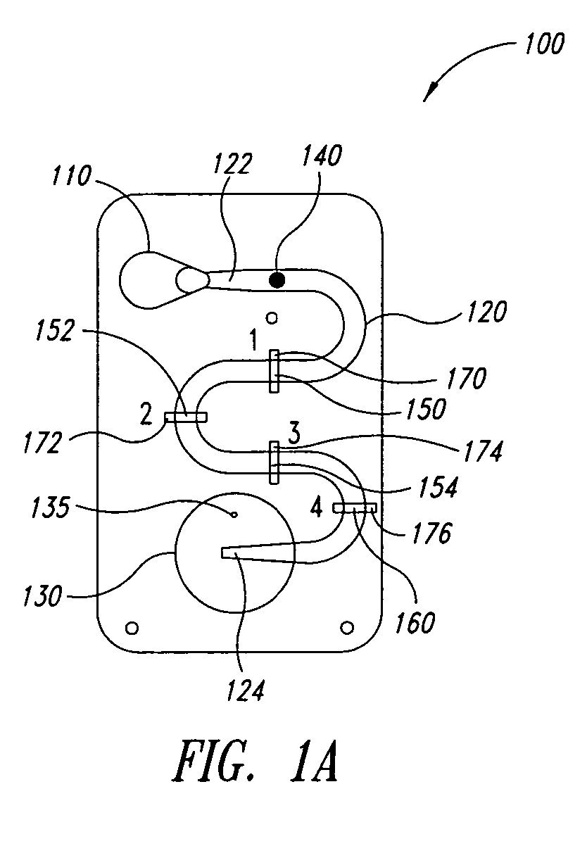
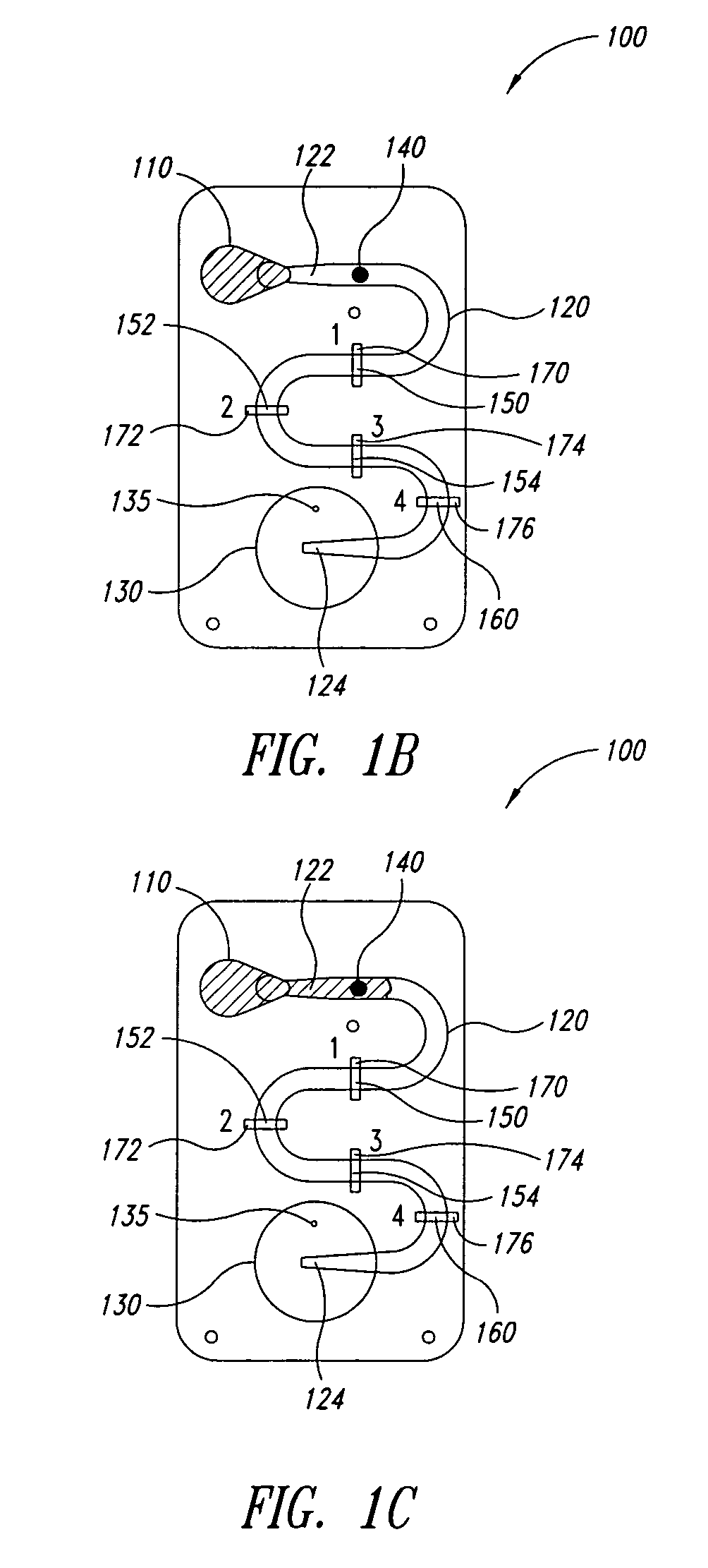
[0041]FIGS. 1A-1F are a series of cross-sectional views illustrating the operation of a microfluidic laminar flow detection strip device 100 in accordance with aspects of the present invention. As shown in FIG. 1A, device 100 comprises a first inlet 110 (for receiving a liquid sample), a microfluidic channel 120 having a first end 122 and a second end 124, wherein first end 122 is fluidly connected to first inlet 110, and a bellows pump 130 fluidly connected to second end 124 of microfluidic channel 120. Microfluidic channel 120 may be straight, as illustrated in FIGS. 5A-5F, or may have a serpentine shape as illustrated in FIG. 1A to provide a longer reaction channel. Bellows pump 130 comprises an absorbent material (not specifically shown), such as cotton, disposed therein. In addition, in the embodiment of FIG. 1A, bellows pump 130 comprises a vent hole 135.

[0042] As illustrated, device 100 is in the form of a cartridge, however, the form of device 100 is not essential to the pre...

second embodiment

[0052]FIGS. 2A-2F are a series of cross-sectional views illustrating the operation of a microfluidic laminar flow detection strip device 200 in accordance with aspects of the present invention. As shown in FIG. 2A, device 200 is similar to device 100 of FIG. 1A and comprises a first inlet 210 (for receiving a liquid sample), a microfluidic channel 220 having a first end 222 and a second end 224, wherein first end 222 is fluidly connected to first inlet 210, and a bellows pump 230 fluidly connected to second end 224 of microfluidic channel 220. Microfluidic channel 220 may be straight, as illustrated in FIGS. 5A-5F, or may have a serpentine shape as illustrated in FIG. 2A to provide a longer reaction channel. As in device 100 of FIG. 1A, bellows pump 230 comprises an absorbent material (not specifically shown) disposed therein.

[0053] Rather than providing a vent hole in bellows pump 230 as in FIG. 1A, device 200 utilizes first and second check valves, 237 and 239, respectively, to pr...

third embodiment

[0064]FIGS. 3A-3F are a series of cross-sectional views illustrating the operation of a microfluidic laminar flow detection strip device in accordance with aspects of the present invention. As shown in FIG. 3A, device 300 is similar to device 100 of FIG. 1A and comprises a first inlet 310 (for receiving a liquid sample), a microfluidic channel 320 having a first end 322 and a second end 324, wherein first end 322 is fluidly connected to first inlet 310, and a bellows pump 330 fluidly connected to second end 324 of microfluidic channel 320. Microfluidic channel 320 may be straight, as illustrated in FIGS. 5A-5F, or may have a serpentine shape as illustrated in FIG. 3A to provide a longer reaction channel. As in device 100 of FIG. 1A, bellows pump 330 comprises an absorbent material (not specifically shown) disposed therein. In addition, in the embodiment of FIG. 1A, bellows pump 330 comprises a vent hole 335.

[0065] In addition, as shown in FIG. 3A, device 300 further comprises a seco...


PUM


Abstract

The present invention relates to microfluidic laminar flow detection strip devices and methods for using and making the same. The disclosed devices comprise: a first inlet; a microfluidic channel having a first end and a second end, wherein the first end is fluidly connected to the first inlet; a bellows pump fluidly connected to the second end of the microfluidic channel, wherein the bellows pump comprises an absorbent material disposed therein; a dried reagent zone within the microfluidic channel, wherein the dried reagent zone comprises a first reagent and a control reagent printed thereon, the first reagent comprising a first detection antibody conjugated to a dyed substrate bead or functionalized for colorimetric development, and the control reagent comprising a control detection antibody conjugated to a dyed substrate bead or functionalized for calorimetric development; a first bound antibody zone within the microfluidic channel, wherein the first bound antibody zone comprises a first bound antibody printed thereon; and a control zone within the microfluidic channel, wherein the control zone comprises a control bound antibody printed thereon.

Description

CROSS-REFERENCE TO RELATED APPLICATION [0001] This application claims the benefit under 35 U.S.C. §119(e) of U.S. Provisional Patent Application No. 60 / 677,531, filed May 3, 2005, where this provisional application is incorporated herein by reference in its entirety.BACKGROUND OF THE INVENTION [0002] 1. Field of the Invention [0003] The present invention relates generally to microfluidic devices, and, more particularly, to microfluidic laminar flow detection strip devices and methods for using and making the same. [0004] 2. Description of the Related Art [0005] Detection of biological or chemical analytes in point-of-care or field testing environments (such as a doctor's office, food or water processing plant, or home setting) offers significant advantages, including obtaining a more rapid result that enables immediate on site intervention based upon the test. However, such environments require that the detection methods be of low cost and simple assay complexity. Preferably, the de...

Claims


Application Information

Patent Timeline
IPC IPC(8): G01N33/53C12M3/00
CPCG01N33/54366G01N33/54386
Inventor GERDES, JOHNBATTRELL, C. FREDERICKHOEKSTRA, DENISE MAXINECLEMMENS, JOHNMORDUE, STEPHEN
Owner PERKINELMER HEALTH SCIENCES INC
Why Eureka
Try Eureka