Universal joint

a universal joint and joint technology, applied in the field of universal joints, can solve the problems of difficult smooth change of the direction the drive wheel b>17/b> travels, difficult to smooth change the direction the drive wheel travels, and problems such as the forgoing, and achieve the effect of less tendency

Inactive Publication Date: 2007-02-22
MITSUYA LAB
View PDF4 Cites 73 Cited by
  • Summary
  • Abstract
  • Description
  • Claims
  • Application Information

AI Technical Summary

Benefits of technology

[0026] According to the fourth characteristic, because the ball portion is subject to a positional limit within the holding hole of the rotation body, the holding hole does not need to be deepened. In consequence, even when the rotation shaft moves toward the rotation body, the rotation shaft has less tendency to come into contact with the opening end of the holding hole. Thus, the opening end of the holding hole is not damaged by the rotation shaft.

Problems solved by technology

If the rotation body 6 rotates while pulling the ball portion 2 inward as described above, the resistance is increased, thereby making it difficult to smoothly change the direction the drive wheel 17 travels.
Thus, a smooth change in the direction the drive wheel 17 travels is made difficult.
In this case, problems as described in the forgoing also arise.
However, when the ball portion 2 is positioned close to the closed end of the holding hole 8, if the rotation shaft 1 moves toward the rotation body 6, disadvantageously, the rotation shaft 1 is pressed against the opening edge of the holding hole 8 and causes damage to the opening edge.

Method used


Image

  • Universal joint
  • Universal joint
  • Universal joint

Examples


Embodiment Construction

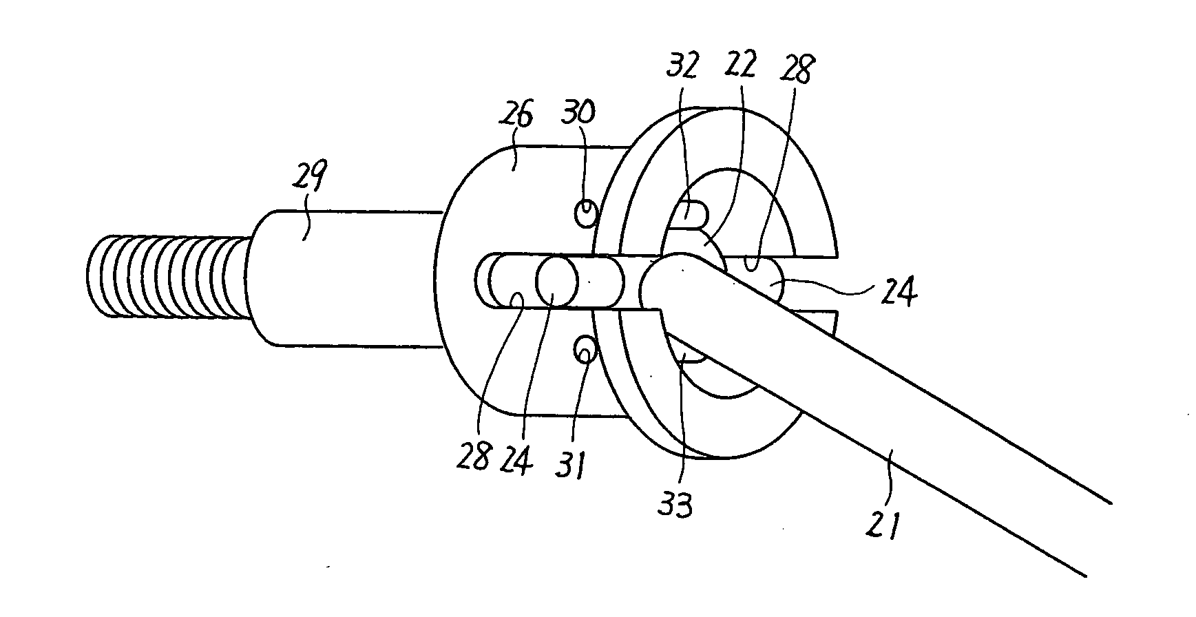
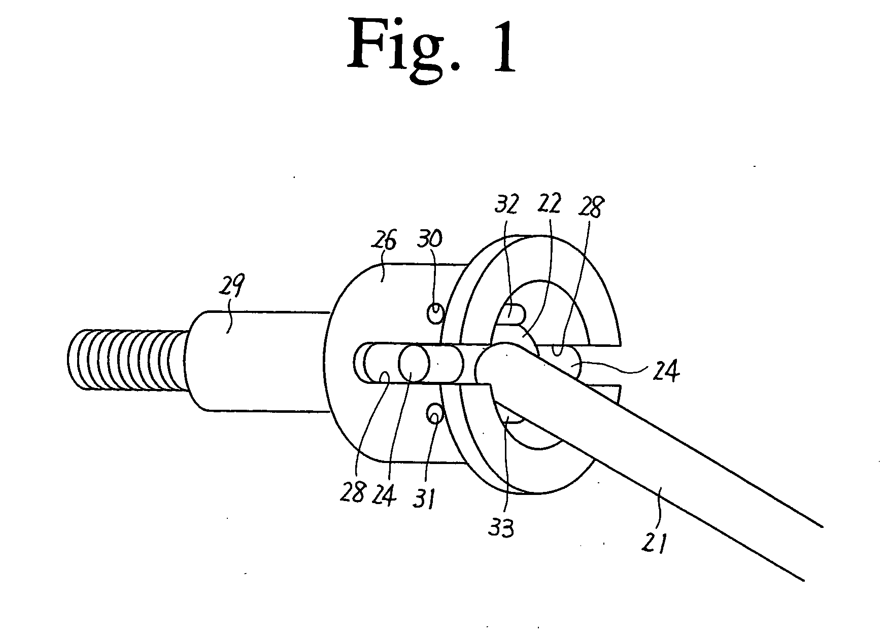
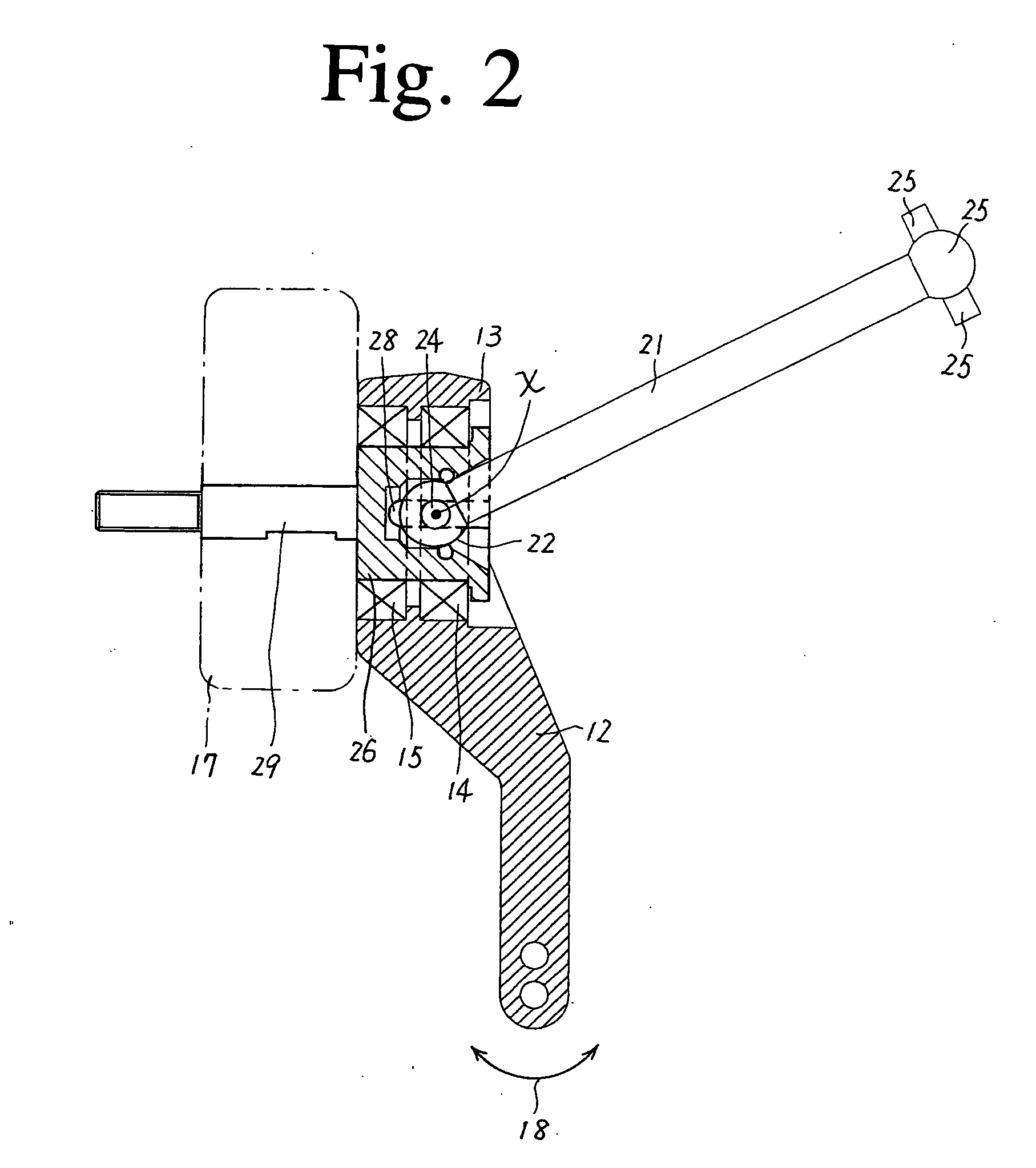
[0035] FIGS. 1 to 3 illustrate an embodiment of using the universal joint of the present invention for a radio-controlled car. The universal joint has ball portions 22 and 23 respectively provided at the ends of a rotation shaft 21. The ball portions 22 and 23 have respective pairs of projections 24 and 25 placed on their diameter lines.

[0036] Further, the two ends of the rotation shaft 21 are respectively coupled to two rotation bodies. One rotation body 26 of the two rotation bodies has features as the present invention, and the other rotation body is the same as that conventionally used. Therefore, a detailed description of the other rotation body is omitted and, when required, a description will be given by using the same reference numbers as those in the description of the conventional example.

[0037] The rotation body 26 is formed in a tubular shape and has a holding hole 27 drilled on the axis line of the rotation body 26. The ball portion 22 is placed in the holding hole 27...


PUM


Abstract

In inexpensive structure, a rotation center of a ball portion provided on a rotation shaft is prevented from moving. A universal joint is provided with a rotation shaft (21) having a ball portion (22) provided at an end thereof and a pair of projections (24, 25) formed on a diameter line of the ball portion (22), and a rotation body (26) having guide grooves (28) formed for receiving insertion of the respective projections of the rotation shaft and a holding hole (27) formed for holding the ball portion (22), the ball portion being rotatable about an axis line of the projections and rotatable while inclining the projections along the guide grooves. In the universal joint pins (32, 33) serving as a stopper are provided in the holding hole for inhibiting the ball portion from slipping off.

Description

BACKGROUND OF THE INVENTION [0001] 1. Field of the Invention [0002] This invention relates to a universal joint having a rotation body and a rotation shaft which cause bending in any direction. [0003] 2. Description of the Related Art [0004]FIG. 4 to FIG. 8 show an example conventionally known as the above type of universal joints. The conventional universal joint in FIGS. 4 to 8 has ball portions 2 and 3 respectively provided at the ends of a rotation shaft 1. The ball portions 2 and 3 have the respective pairs of projections 4 and 5 formed on the diameter lines of the ball portions 2 and 3. [0005] Two rotation bodies 6 and 7, which are coupled to the rotation shaft 1, are formed in a tubular shape and respectively have holding holes 8 and 9 formed on their axis. The holding holes 8 and 9 respectively receive the ball portions 2 and 3 and allow them to slide in the axis direction. The rotation body 6 has guide grooves 10 formed in positions 180 degrees out of phase with each other,...

Claims


Application Information

Patent Timeline
Patent Type & Authority Applications(United States)
IPC IPC(8): F16D3/20
CPCF16D3/2052
Inventor FURUSAWA, TOSHIO
Owner MITSUYA LAB
Why Eureka
Try Eureka