Laser welding of overlapping metal workpieces assisted by varying laser beam parameters

a technology of laser beam and overlapping metal workpiece, which is applied in the field of laser welding to achieve the effects of reducing solubility, improving strength and properties, and positive impacting the strength and other mechanical properties of laser weld joints

Inactive Publication Date: 2018-01-11
GM GLOBAL TECH OPERATIONS LLC
View PDF6 Cites 20 Cited by
  • Summary
  • Abstract
  • Description
  • Claims
  • Application Information

AI Technical Summary

Benefits of technology

[0016]The repeated varying of at least one of the laser beam parameters, and in some instances all of them, positively impacts the strength and other mechanical properties of the obtained laser weld joint. Such results can be realized since repeatedly varying at least one of the laser beam parameters helps restrain the temperature of the molten metal weld pool, thereby allowing the weld pool to be kept at lower temperature than would otherwise be the case in the absence of repeatedly varying the laser beam parameter(s), and also acts to agitate the molten metal weld pool. The ability to regulate and maintain a lower temperature in the molten metal weld pool supports better strength and properties in the obtained laser weld joint by reducing the solubility of certain gaseous substances (e.g., zinc, hydrogen, etc.) in the weld pool. And, when lower quantities of dissolved gasses are dissolved in the molten metal weld pool, there is less of a tendency for porosity to form within the laser weld joint as the weld pool solidifies. Additionally, the induced agitation of the molten metal weld pool helps promote the release of gases trapped within the molten material of the weld pool. The evolution of trapped gasses from the molten metal weld pool is another action that can inhibit porosity formation in the obtained laser weld joint. Other weld joint deficiencies—such as spatter, blowholes, and undercut joints—may also be minimized.

Problems solved by technology

The various metal workpieces included in each of the aforementioned workpiece stack-ups presents challenges when trying to join the workpieces together with a laser beam during assorted implementations of laser welding including remote laser welding and conventional laser welding.

Method used


Image

  • Laser welding of overlapping metal workpieces assisted by varying laser beam parameters
  • Laser welding of overlapping metal workpieces assisted by varying laser beam parameters
  • Laser welding of overlapping metal workpieces assisted by varying laser beam parameters

Examples


Embodiment Construction

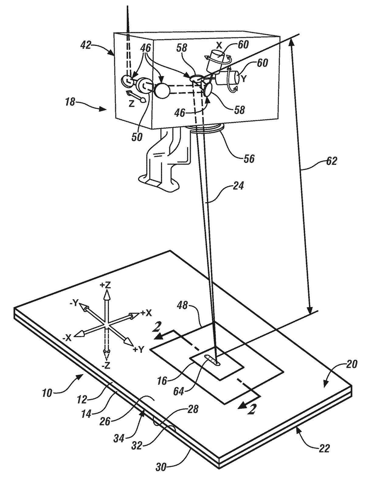
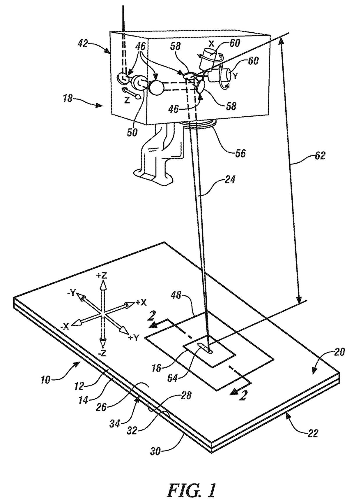
[0031]The disclosed method of laser welding a workpiece stack-up comprised of two or more overlapping metal workpieces involves forming a laser weld joint by repeatedly varying at least one of the power level of the laser beam, the travel speed of the laser beam, or the focal position of the laser beam while advancing a beam spot of a laser beam relative to a top surface of the workpiece stack-up along a beam travel pattern. Any type of laser welding apparatus, including remote and conventional laser welding apparatuses, may be employed to form the laser weld joint while repeatedly varying the designated beam parameter(s). The laser beam may be a solid-state laser beam or a gas laser beam depending on the characteristics and compositions of the metal workpieces being joined and the laser welding apparatus being used. Some notable solid-state lasers that may be used are a fiber laser, a disk laser, a direct diode laser, and a Nd:YAG laser, and a notable gas laser that may be used is ...


PUM

PropertyMeasurementUnit
travel speedaaaaaaaaaa

Abstract

A method of laser welding a workpiece stack-up that includes at least two overlapping metal workpieces is disclosed. The method includes advancing a beam spot of a laser beam relative to a top surface of the workpiece stack-up and along a beam travel pattern to form a laser weld joint, which is comprised of resolodified composite metal workpiece material, that fusion welds the metal workpieces together. And, while the beam spot is being advanced along the beam travel pattern, between a first point and a second point, which may or may not encompass the entire beam travel pattern, at least one of the following laser beam parameters is repeatedly varied: (1) the power level of the laser beam; (2) the travel speed of the laser beam; or (3) the focal position of the laser beam relative to the top surface of the workpiece stack-up.

Description

TECHNICAL FIELD[0001]The technical field of this disclosure relates generally to laser welding and, more particularly, to a method of laser welding together two or more overlapping metal workpieces in which all of the overlapping metal workpieces in the stack-up are steel workpieces, aluminum workpieces, or magnesium workpieces.BACKGROUND[0002]Laser welding is a metal joining process in which a laser beam is directed at a metal workpiece stack-up to provide a concentrated energy source capable of effectuating a weld joint between the overlapping constituent metal workpieces. In general, two or more metal workpieces are first aligned and stacked relative to one another such that their faying surfaces overlap and confront to establish a faying interface (or faying interfaces) that extends through an intended weld site. A laser beam is then directed towards and impinges a top surface of the workpiece stack-up. The heat generated from the absorption of energy from the laser beam initiat...

Claims


Application Information

Patent Timeline
Patent Type & Authority Applications(United States)
IPC IPC(8): B23K26/06B23K26/21B23K26/322B23K103/04B23K103/08B23K103/10B23K103/16
CPCB23K26/322B23K2203/04B23K2203/10B23K26/21B23K2203/166B23K26/0626B23K2203/15B23K26/082B23K26/0884B23K26/244B23K26/32B23K2101/006B23K2101/18B23K2101/34B23K2103/04B23K2103/10B23K2103/15B23K2103/166B23K2103/20
Inventor YANG, DAVIDTAO, WU
Owner GM GLOBAL TECH OPERATIONS LLC
Why Eureka
Try Eureka