Rail wheel measurement

Inactive Publication Date: 2007-02-22
GENERAL ELECTRIC CO
View PDF12 Cites 15 Cited by
  • Summary
  • Abstract
  • Description
  • Claims
  • Application Information

AI Technical Summary

Problems solved by technology

Rail vehicle wheels suffer wear over time due to their contact with the rail.
The treads wear as a result of their contact with the top of the rail, particularly in the event of the wheel slipping

Method used


Image

  • Rail wheel measurement
  • Rail wheel measurement

Examples


Embodiment Construction

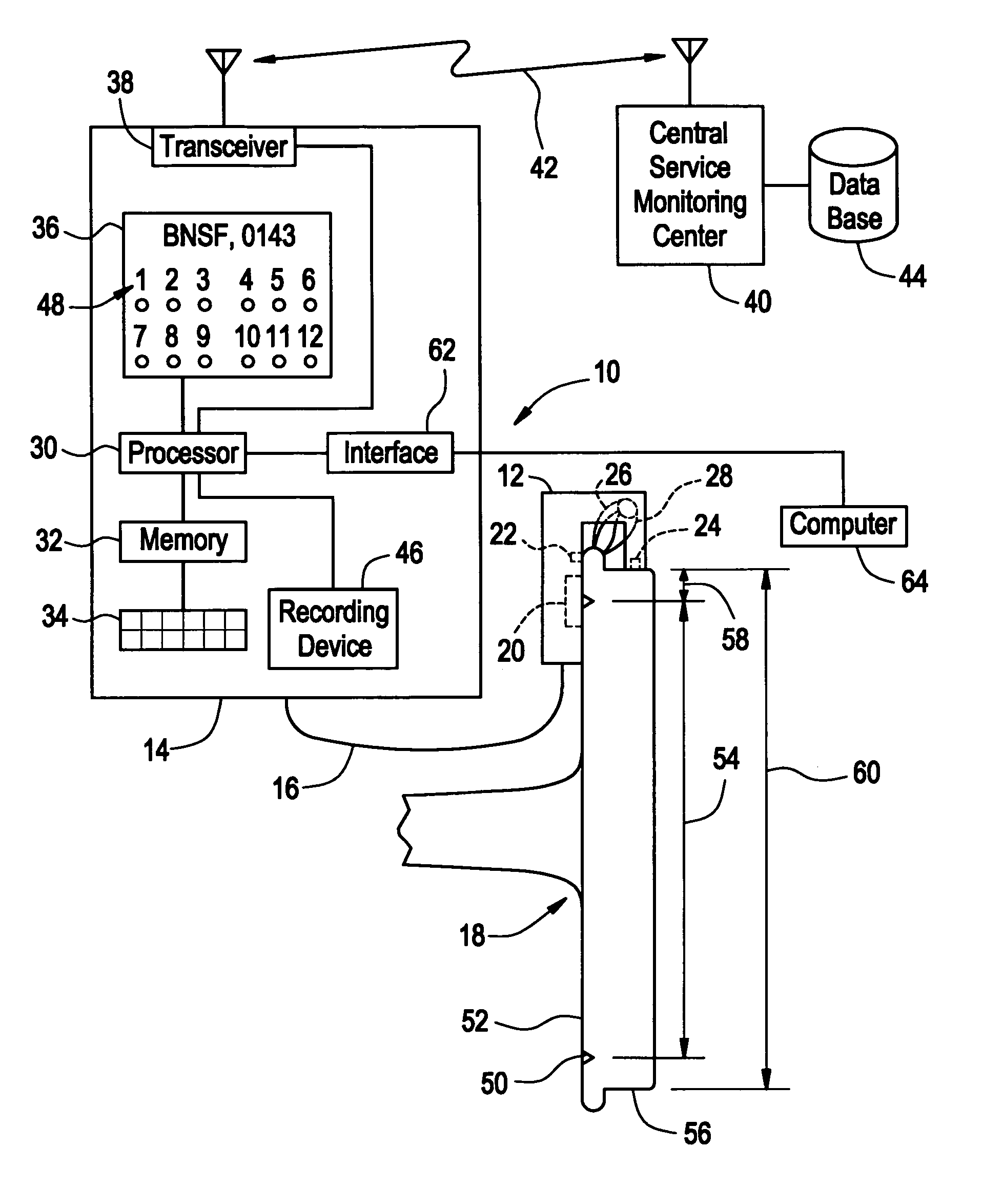
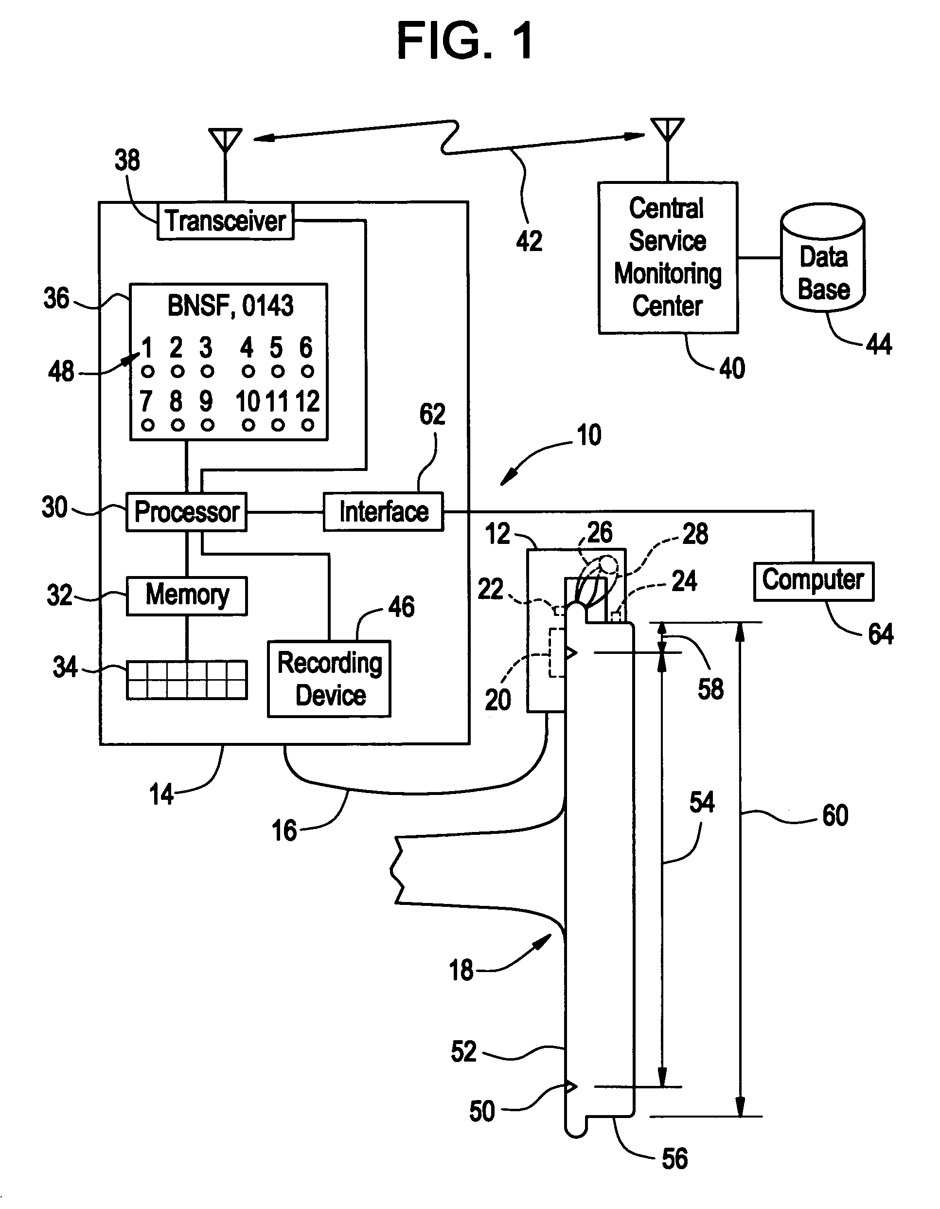
[0005] The use of electronic rail wheel gauges to measure various rail wheel dimensions has allowed more accurate and repeatable measurements to be achieved compared to using conventional mechanical rail wheel measurement gauges. However, the rail wheel measurement information providing using electronic rail wheel gauges has been underutilized for making rail wheel service decisions, such as predicting remaining wheel life. In the past, rail wheel service decisions may have been made based on a measured dimension's proximity to a minimum dimension size, for example, as specified by the FRA, without regard for a wear rate of the measured wheel or measurement interval. However, such techniques may allow useable wheel wear life to be sacrificed. The inventors of the present invention have innovatively realized that information derived from electronic rail wheel measurements may be used in conjunction with historical information related to the wheel being measured to more accurately pre...


PUM


Abstract

A method of determining a remaining service life for a rail wheel (18) of a railway vehicle using an electronic rail wheel (18) wear gauge (10) mountable on the rail wheel for measuring at least one rail wheel dimension. The method includes measuring a rail wheel dimension and processing the measured wheel dimension relative to an allowable wear dimension. The method also includes accessing a historical wheel wear rate database (44) relating to the rail wheel and predicting a remaining service life of the wheel based on the historical wheel wear rate data and the processed wheel dimension.

Description

FIELD OF THE INVENTION [0001] This invention relates generally to the field of rail transportation and, more particularly, to an electronic device for measuring rail wheel dimensions. BACKGROUND OF THE INVENTION [0002] A typical train includes one or more locomotives pulling a plurality of load cars. Each vehicle in the train includes a plurality of steel wheels that roll along the metal rail as the train is propelled along the track. Proper interaction between the wheel and the rail is critical for safe, reliable, efficient operation of the train. [0003] A rail includes a bottom mounting flange, a top railhead that makes contact with the vehicle wheel, and a flange interconnecting the flange and the railhead. A vehicle wheel includes a center hub mounted onto the vehicle axle, a plate extending outwardly from the hub, and an outer rim surrounding the plate for making contact with the rail. The rim includes an outside diameter tread that may be flat or tapered and a flange extending...

Claims


Application Information

Patent Timeline
IPC IPC(8): G06F19/00
CPCG01B21/02B61K9/12G01M17/10
Inventor MOFFETT, JEFFREY PAULMIYASHIRO, JASON KEANUENUE YAMATOSUBRAMANIAM, SIVAKUMARBROOKS, JEFFREY RICHARDTOMARO, ANTHONY M.
Owner GENERAL ELECTRIC CO
Why Eureka
Try Eureka