Table saw

a table saw and table technology, applied in the field of table saws, can solve the problems of complicated height adjustment procedure waste of time, reading errors, etc., and achieve the effect of knowing the current height of the saw blade, facilitating the performance of cutting work, and easy and convenient adjustmen

Inactive Publication Date: 2007-03-01
REXON IND CORP LTD
View PDF20 Cites 9 Cited by
  • Summary
  • Abstract
  • Description
  • Claims
  • Application Information

AI Technical Summary

Benefits of technology

[0007] The present invention has been accomplished under the circumstances in view. It is an objective of the present invention to provide a table saw, which quickly and accurately indicates a height of the saw blade.
[0009] In the embodiments of the present invention, the displacement of the saw blade is a height change of the saw blade relative to the worktable. The scale member has a plurality of graduations for indicating the height of the saw blade relative to the worktable. When the height of the saw blade is changed, the graduations of the scale member are moved correspondingly, thereby indicating the real-time height of the saw blade. Therefore, the table saw of the present invention enables the user to know the current height of the saw blade easily and conveniently, and then allows the user to adjust the saw blade to a predetermined height quickly and accurately. This facilitates the performance of cutting work a lot.

Problems solved by technology

This saw blade height adjustment procedure is complicated, and wastes much time.
Further, using a measuring tape to measure the height of the saw blade may result in a reading error.
Therefore, the aforesaid saw blade height measuring and adjusting method brings inconvenience to the user.
However, the markings may be worn off by using of the saw blade.
However, the design is still not satisfying in application.
When making the alignment, the teeth of the saw blade may injure the user's hand accidentally.

Method used


Image

  • Table saw
  • Table saw
  • Table saw

Examples


Embodiment Construction

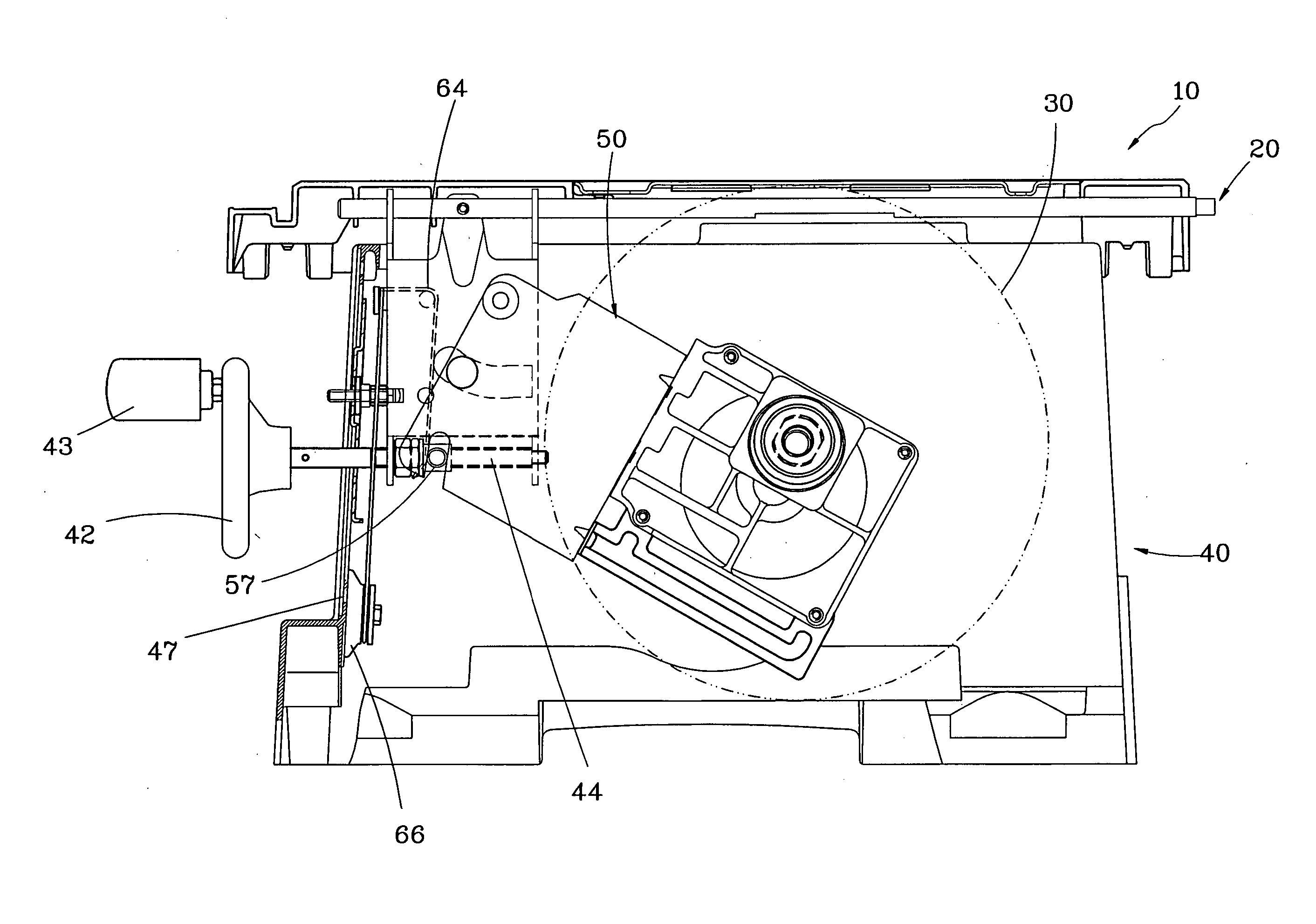
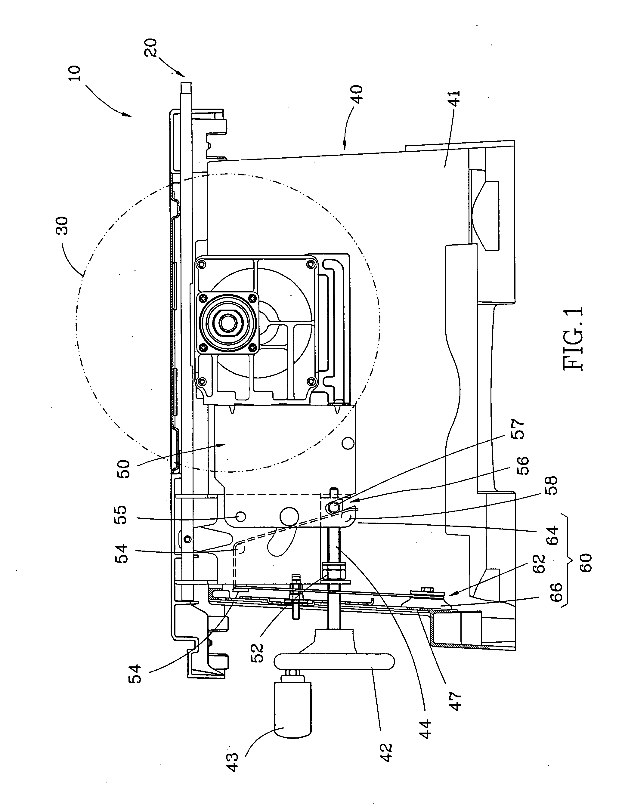
[0015] As shown in FIG. 1, a table saw 10 in accordance with a first preferred embodiment of the present invention comprises a worktable 20, a rotary saw blade 30, a base 40, a saw blade holder 50, and an indicator 60.

[0016] The worktable 20 is adapted to carry a workpiece (not shown). The worktable 20 has a cutting slot (not shown) through which the rotary saw blade 30 extends for cutting the workpiece.

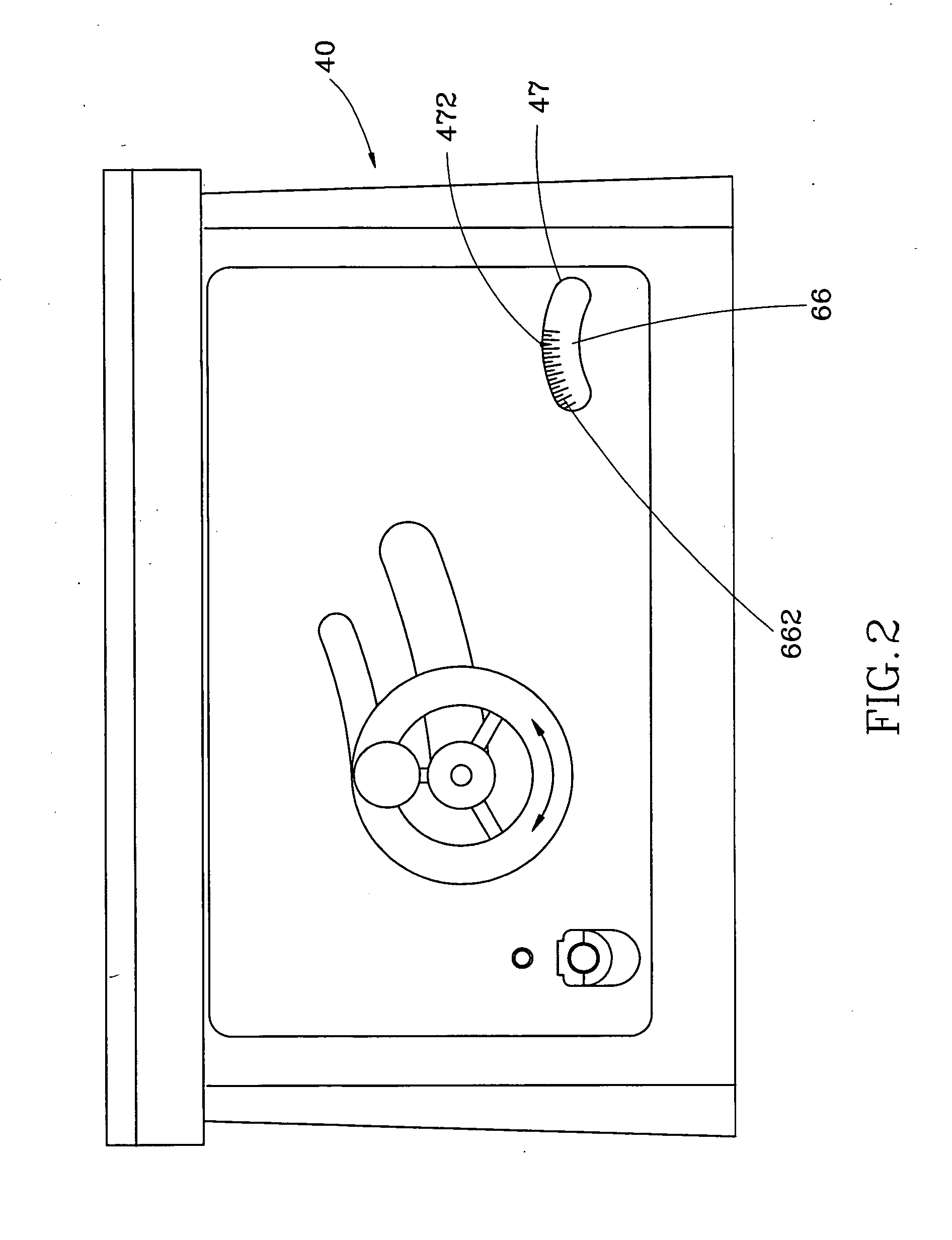
[0017] The base 40 is provided at the bottom side of the worktable 20 to support the worktable 20. The saw blade holder 50 carries a motor (not shown). The saw blade 30 is mounted to the saw blade holder 50 and rotated by the motor for cutting the workpiece. Moreover, the saw blade holder 50 has a mounting member 55 and a guide slot 56. By means of using the mounting member 55 as a pivotal point of the saw blade holder 50, the saw blade holder 50 is pivotally disposed inside a chamber 41 of the base 40 below the worktable 20. A threaded rod 44 is mounted inside the chamber 41. A mo...


PUM

PropertyMeasurementUnit
biasing forceaaaaaaaaaa
transparentaaaaaaaaaa
heightaaaaaaaaaa

Abstract

A table saw includes a worktable, a base supporting the worktable, a rotary saw blade extending through a cutting slot of the worktable, a saw blade holder pivotally disposed inside the base and mounting with the rotary saw blade, and an indicator having a scale member mounted to the table saw, and a connecting member. The connecting member has a first end connected to a non-pivotal point of the saw blade holder, and a second end connected to the scale member. When the saw blade holder is rotated, the saw blade holder results in a displacement of the saw blade and a movement of the scale member corresponding to the displacement of the saw blade through actuation of the connecting member.

Description

BACKGROUND OF THE INVENTION [0001] 1. Field of the Invention [0002] The present invention relates to a table saw, and more particularly to a table saw having an indicator capable of indicating a displacement of a saw blade. [0003] 2. Description of the Related Art [0004] A conventional table saw generally comprises a worktable for carrying a workpiece, a base for supporting the worktable, a saw blade holder pivotally mounted inside the base below the worktable, and a rotary saw blade mounted to the saw blade holder and extending through a cutting slot of the worktable for cutting the workpiece. The saw blade holder has a motor operable to rotate the saw blade. According to a specific cutting requirement, the user can make the saw blade holder pivot to vertically move the saw blade relative to the worktable to adjust the saw blade to a desired height relative to the worktable; thereby the workpiece can be processed by various cutting heights. [0005] In order to know the accurate heig...

Claims


Application Information

Patent Timeline
Patent Type & Authority Applications(United States)
IPC IPC(8): B23D45/06
CPCB23D45/068Y10T83/7872Y10T83/857Y10T83/7705Y10T83/7726Y10T83/773
Inventor CHEN, JUNG-HUO
Owner REXON IND CORP LTD
Why Eureka
Try Eureka