Single disc liquid fertilizer opener

a liquid fertilizer and opener technology, applied in the field of single disc liquid fertilizer delivery, can solve the problems of high side loading force, failure to teach a directed placement method or apparatus, fertilizer splashing on the disc and potentially the seed, etc., to eliminate premature mechanical failure of the system and minimize the chance of fertilizer feed tube failure

Active Publication Date: 2007-03-01
MARTIN HOWARD D
View PDF17 Cites 87 Cited by
  • Summary
  • Abstract
  • Description
  • Claims
  • Application Information

AI Technical Summary

Benefits of technology

[0030] It is another objective of the method and apparatus disclosed to shield the fertilizer feed tube to minimize opportunities for fertilizer feed tube failure due to impact with field stubble, clods and stones.
[0031] It is another objective of the method and apparatus disclosed to eliminate premature mechanical failure of the system by allowing improved access and maintenance.

Problems solved by technology

Both patents fail to teach a method or apparatus for directed placement of liquid fertilizer and incorporated within the soil therein.
This mounting method results in high side loading forces at the point of attachment for each unit.
Placement of fertilizer using the seed tube as taught by Wendling would result in splashing fertilizer on the disc and potentially the seed.
The above prior art alone or in combination fails to teach a planter row unit mounted attachment for directed delivery and incorporation of liquid fertilizer in no or minimum till conditions which is compact and light in weight.
The prior art fails to teach an apparatus that minimizes interference with seed placement while minimizing soil disruption for placement of said fertilizer.
The prior art fails to teach a liquid fertilizer opener that creates minimal side loading using a symmetrical but opposite mounting structure.

Method used


Image

  • Single disc liquid fertilizer opener
  • Single disc liquid fertilizer opener
  • Single disc liquid fertilizer opener

Examples


Embodiment Construction

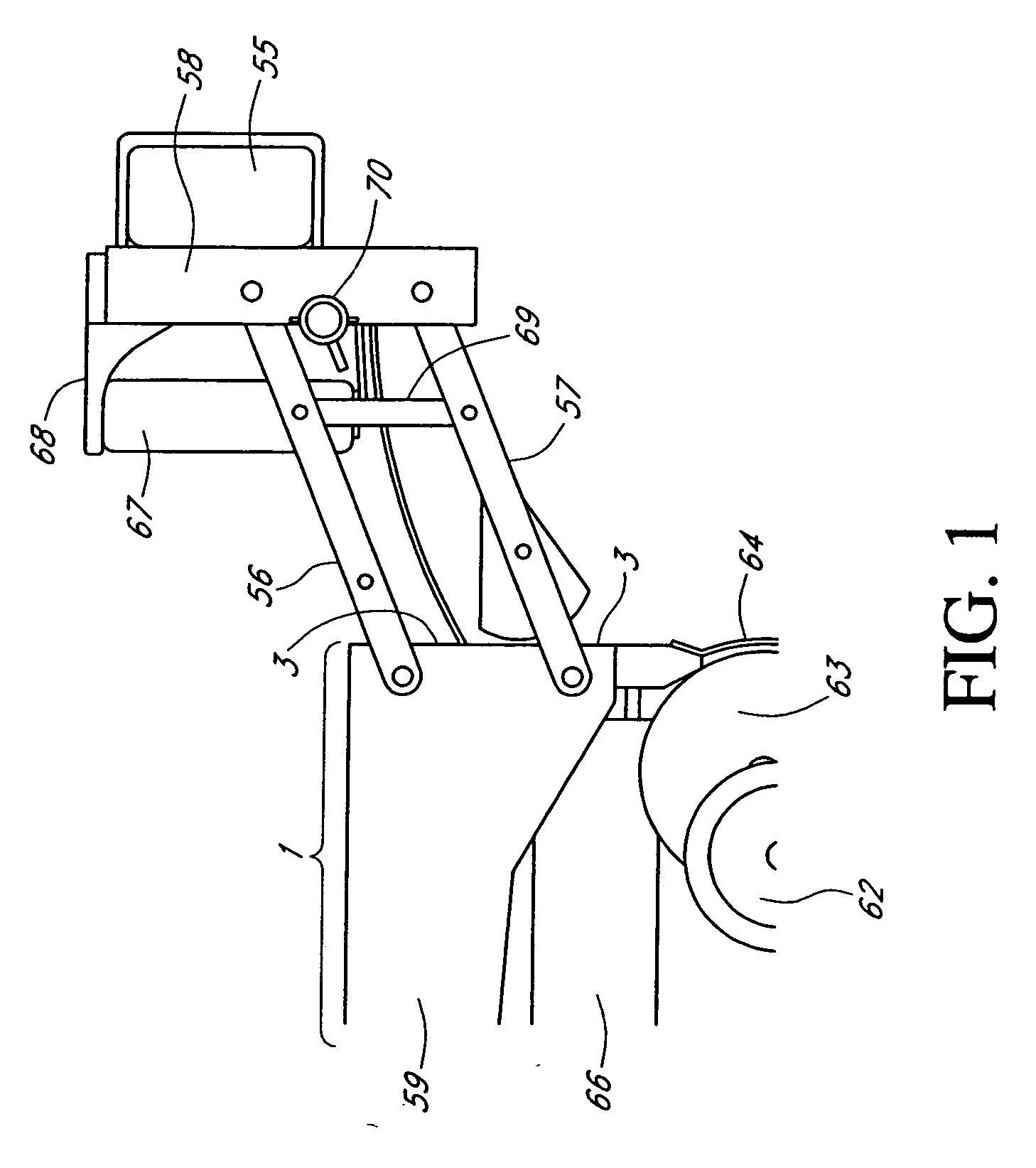
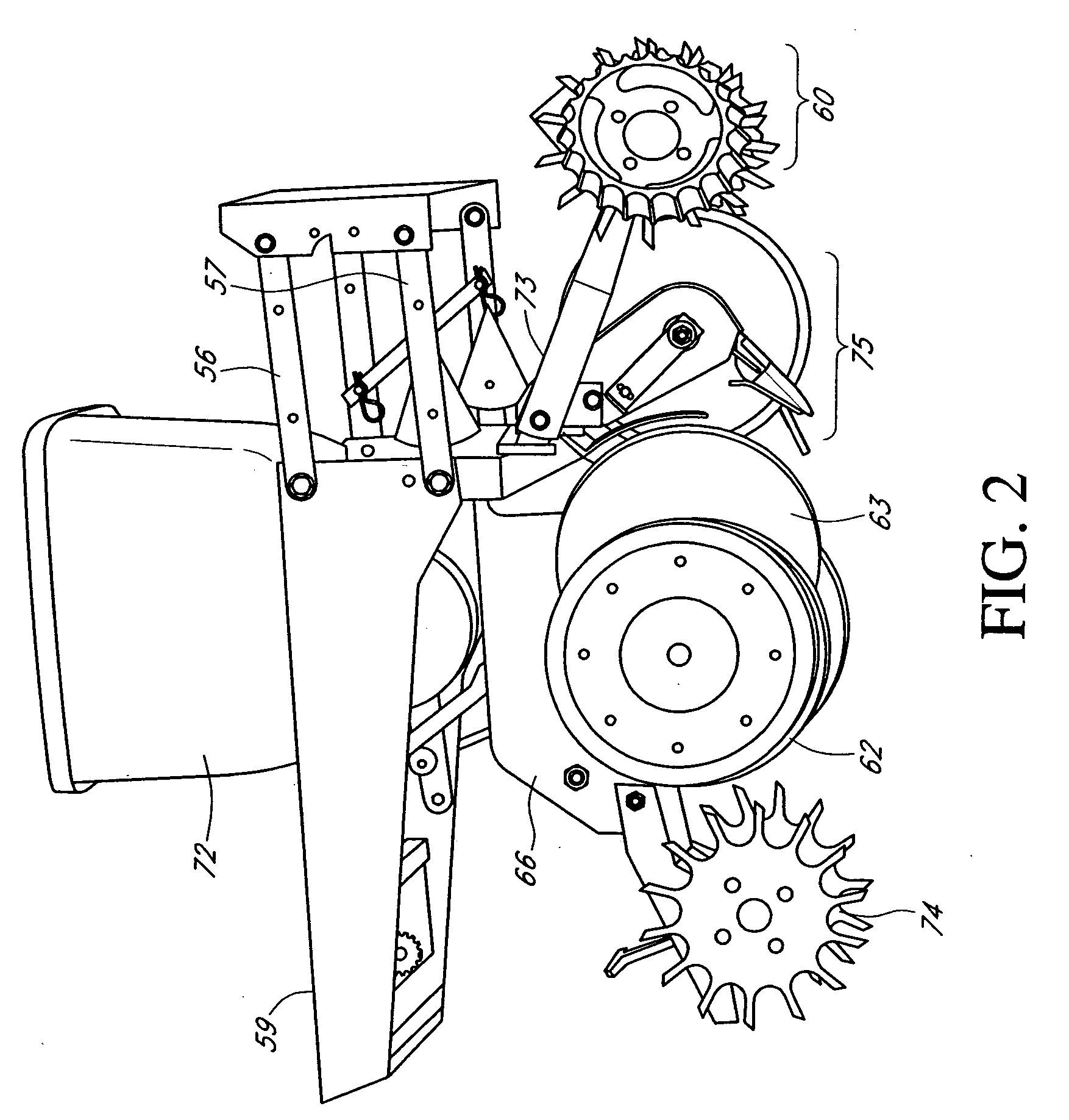
[0047] Referring now to the drawings, wherein like reference numerals designate identical or corresponding parts throughout the several views, FIGS. 1-3 as presented disclose and describe a typical planter row unit upon which the invention may be mounted wherein the row units 1 are attached to a tool bar or main frame 58 via a parallel linkage 56, 57. FIG. 1 shows the planter row unit 1 is traditionally mounted behind and to the planter mainframe 55 by means of a four bar linkage. This four bar linkage is referred to as a parallel linkage and labeled an upper link 56 and a lower link 57. This configuration allows the planter row unit 1 to flex during operation. The linkage system composed of upper link 56 and lower link 57 connects the center mount of the row unit frame 58 to seed frame hopper 59. Those practiced in the arts will understand that with minor modification the apparatus and method disclosed herein can be also adapted to planter row units 1 mounted to the front of the ma...


PUM


Abstract

A method and apparatus to be mounted upon a planter row unit for delivering liquid fertilizer to the bottom of a trench without contacting the seed to be planted is disclosed and claimed. The system as claimed and described is adapted for mounting to substantially all modern row units employing floating row units. The method and apparatus as described does not interfere with existing down pressure or seed placement systems as found on modern row crop planters. As described and implemented, the method and apparatus is more compact and lighter in weight than the prior art. The attached assembly for a seed planting unit works in combination with a seed trench opener to form a trench for the deposit of liquid fertilizer offset from and parallel to the later formed seed trench. The apparatus allows directed liquid fertilizer delivery in close proximity to the seed trench with minimal disruption of said seed trench. The attachment includes a single disk blade disposed forward of the seed trench forming unit. The single disk blade is disposed at an angle of four degrees or less from the line defining the direction of travel of the seed planting implement in combination with a furrow strap. The attachment includes a selectively adjustable down force structure and a selectively adjustable depth control mechanism.

Description

CROSS REFERENCE TO RELATED APPLICATIONS [0001] (Not applicable) [0002] None FIELD OF THE INVENTION [0003] The apparatus and method described herein are generally applicable to the field of agricultural equipment. The embodiments shown and described herein are more particularly for improved delivery of liquid fertilizer as used with seed planter row units. STATEMENT REGARDING FEDERALLY SPONSORED RESEARCH OR DEVELOPMENT [0004] No federal funds were used to develop or create the invention disclosed and described in the patent application. REFERENCE TO SEQUENCE LISTING, A TABLE, OR A COMPUTER PROGRAM LISTING COMPACT DISK APPENDIX [0005] Not Applicable BACKGROUND OF THE INVENTION [0006] The invention as described herein is for attachment to a planter row unit to be used in minimum or no-till conditions. Over the past forty years there has been a migration in agriculture from full tillage prior to planting to no or minimum tilled planting. Full tillage operations may have included multipl...

Claims


Application Information

Patent Timeline
Patent Type & Authority Applications(United States)
IPC IPC(8): A01C23/00
CPCA01C5/064Y02P60/144A01C23/025A01C7/006A01C7/06Y02P60/23Y02P60/14Y02P60/20
Inventor MARTIN, HOWARD D.
Owner MARTIN HOWARD D
Why Eureka
Try Eureka