Add roller for a fiber placement machine

Inactive Publication Date: 2007-03-01
INGERSOLL MACHINE TOOLS
View PDF3 Cites 69 Cited by
  • Summary
  • Abstract
  • Description
  • Claims
  • Application Information

AI Technical Summary

Benefits of technology

[0029] Where a fiber tow has a tow thickness, and an add roller, according to the invention, includes one or more protruding flanges, or other types of protrusions, extending outward from a peripheral surface of the add roller for contacting the feed roller along side of the fiber tow, a method, according to the invention, may include placing the protruding flange, or flanges, into driving contact with the feed surface of the feed roller.
[0030] A method, according to the invention, may include mounting a plurality of add roller actuators, according to the invention, with each add roller actuator having an add roller attached thereto, in an add roller mounting frame adapted for removable attachment to the fiber placement head, to thereby form an add roller module. The method may also include mounting the add roller module in the fiber placement head, and selectively operating one or more of the plurality of

Problems solved by technology

The components of the automated fiber placement machine which perform and control the cut/add process are incapable of instantaneously cutting or adding a tow to the band of material, due to inherent and unavoidable lag times or other latencies in the operation of mechanical, hydraulic, pneumatic, or electrical actuation and control components of the automated fiber placement machine.
These unavoidable and inherent latencies result in the end of a cut or added tow often being positioned well outside of the tolerances required for constructing the composite structure where on-the-fly cut/add is attempted at full operating speed using prior fiber placement machines.
The problems described above, with regard to cut/add operations, are also encountered in other operations performed at high-speed on-the-fly during fabrication of a composite structure, such as changing tension, temperature, or pressure applied on a tow or the material band during automated fiber placement.
Although apparatuses and methods built and operated in accordance with the Assignee's commonly assigned U.S. patent application Ser. No. 11/111,498, provides significant improvements in the ac

Method used


Image

  • Add roller for a fiber placement machine
  • Add roller for a fiber placement machine
  • Add roller for a fiber placement machine

Examples


Embodiment Construction

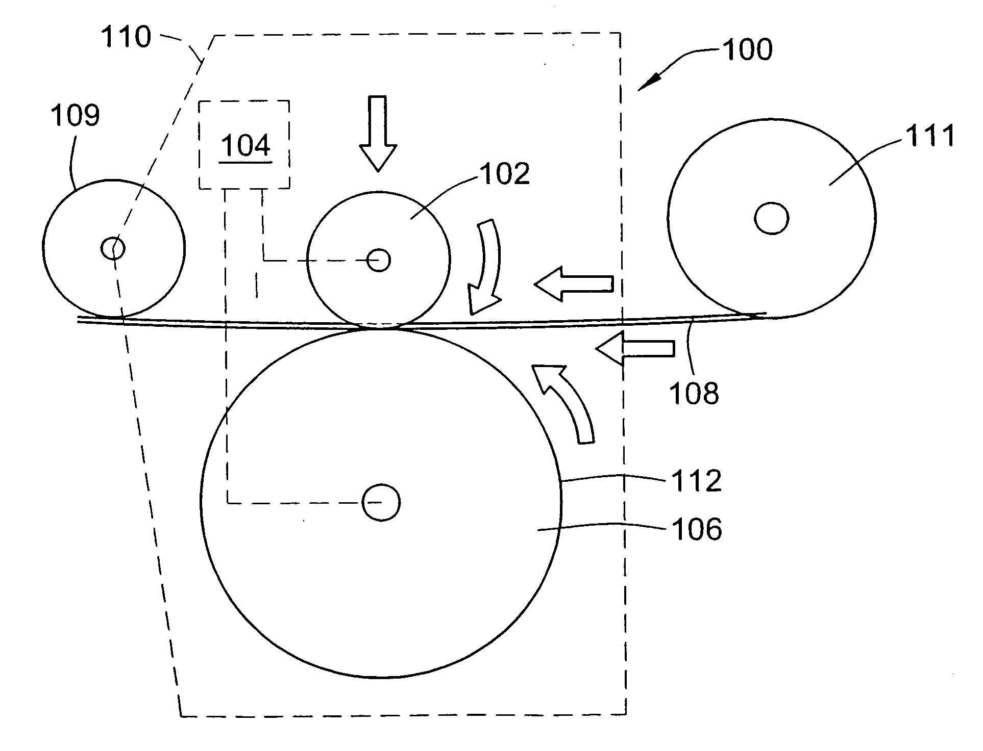
[0038]FIGS. 4 and 5 illustrate a first exemplary embodiment of an add roller apparatus 100, according to the invention, in which an add roller 102 is operatively connected by a drive arrangement 104, to a feed roller 106, of a fiber placement head 110 of a fiber placement machine (represented by the fiber placement head 110 in FIGS. 4 and 5), for clamping and driving a tow 108, extending from a spool 111, in such a manner that the peripheral speeds of the add roller 102 and the tow 108 are more quickly, efficiently, and effectively, brought up to the same peripheral speed as the feed roller 106 and the compaction roller 109 of the fiber placement head 110. The drive arrangement 104 is operatively connected between the feed roller 106 and the add roller 102, and configured in such a manner that prior to, or substantially concurrently with the add roller 102 is accelerated toward a desired peripheral speed matching the peripheral speed of a feed surface 112 of the feed roller 106. In ...


PUM

PropertyMeasurementUnit
Thicknessaaaaaaaaaa
Forceaaaaaaaaaa
Widthaaaaaaaaaa

Abstract

An apparatus and invention are provided for accelerating an added tow to match the lay-down speed of other tows exiting a compaction roller of a fiber placement head, by driving the added tow with an add roller operatively coupled to be driven at the same peripheral speed as a feed roller having a peripheral speed matching the peripheral speed of the compaction roller.

Description

CROSS-REFERENCE TO RELATED PATENT APPLICATIONS [0001] This patent application claims the benefit of U.S. Provisional Patent Application No. 60 / 711,224, filed Aug. 25, 2005, which includes as an attachment thereto a copy of U.S. patent application Ser. No. 11 / 111,498, filed Apr. 21, 2005, which claims the benefit of U.S. Provisional Patent Application No. 60 / 563,921, filed Apr. 21, 2004, with the teachings and disclosures of all of these related patent applications being incorporated herein in their entireties by reference thereto.FIELD OF THE INVENTION [0002] This invention relates to the forming of composite structures with automated fiber placement machines, and more particularly to adding a tow of material on-the-fly. BACKGROUND OF THE INVENTION [0003] Automated fiber placement machines are widely used to manufacture parts, components and structures from composite material. The materials used in automated fiber placement are typically composed of longitudinal fibers and resin con...

Claims


Application Information

Patent Timeline
IPC IPC(8): B29C70/34
CPCB29C70/382B29C70/543Y10T156/1062Y10T156/1348Y10T156/1075Y10T156/1788
Inventor TINGLEY, MARK CURTIS
Owner INGERSOLL MACHINE TOOLS
Why Eureka
Try Eureka