Heatsink having porous fin

a technology of heatsinks and fins, which is applied in the field of heatsinks, can solve the problems of increasing the production cost of heatsinks, limiting the number of fins /b> and the surface area of fins, and achieves the effects of improving the heat dissipation ability, improving the heat dissipation effect, and improving the surface area

Inactive Publication Date: 2007-03-01
KUO CHING LIN
View PDF8 Cites 7 Cited by
  • Summary
  • Abstract
  • Description
  • Claims
  • Application Information

AI Technical Summary

Benefits of technology

[0006] The primary purpose of the present invention is to provide a heatsink structure which conquers the inherent limitation of conventional heatsinks using thin narrow fins without resorting to the use of expensive materials.
[0007] A heatsink according to the present invention has its fins made from metallic plates having multiple cavities of irregular shapes and dimensions dispersed within the metallic plates. For fins made from these porous plates, these cavities or pores significantly increase the surface areas of the fins exposed to the air and these fins, therefore, have a superior heat dissipation capability than those fins made of the same material but with no pores. When operated with an auxiliary fan, the pores of the fins provide additional passages to the air flow and the fins are able to achieve a better wind-chill effect.

Problems solved by technology

However, it should also be obvious that the conventional technique has a certain limitation in terms of the number of fins 20 and the surface area of the fins 20.
This approach inevitably increases the production cost of the heatsinks and, therefore, most manufacturers usually employ an auxiliary fan (as shown in FIG. 3) to increase the air flow and, consequently, the heat dissipation capability of the heatsinks.

Method used


Image

  • Heatsink having porous fin
  • Heatsink having porous fin
  • Heatsink having porous fin

Examples


Embodiment Construction

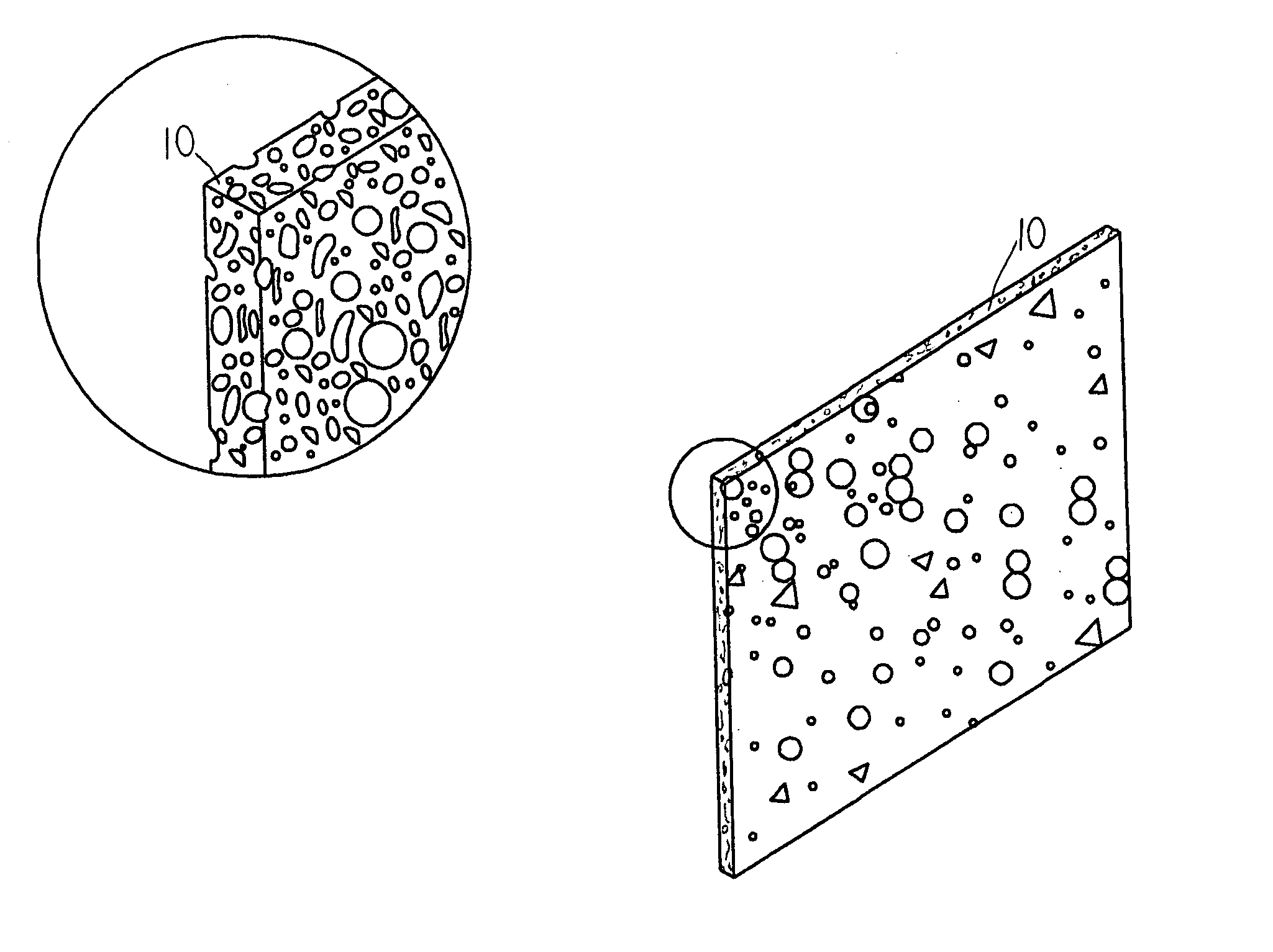
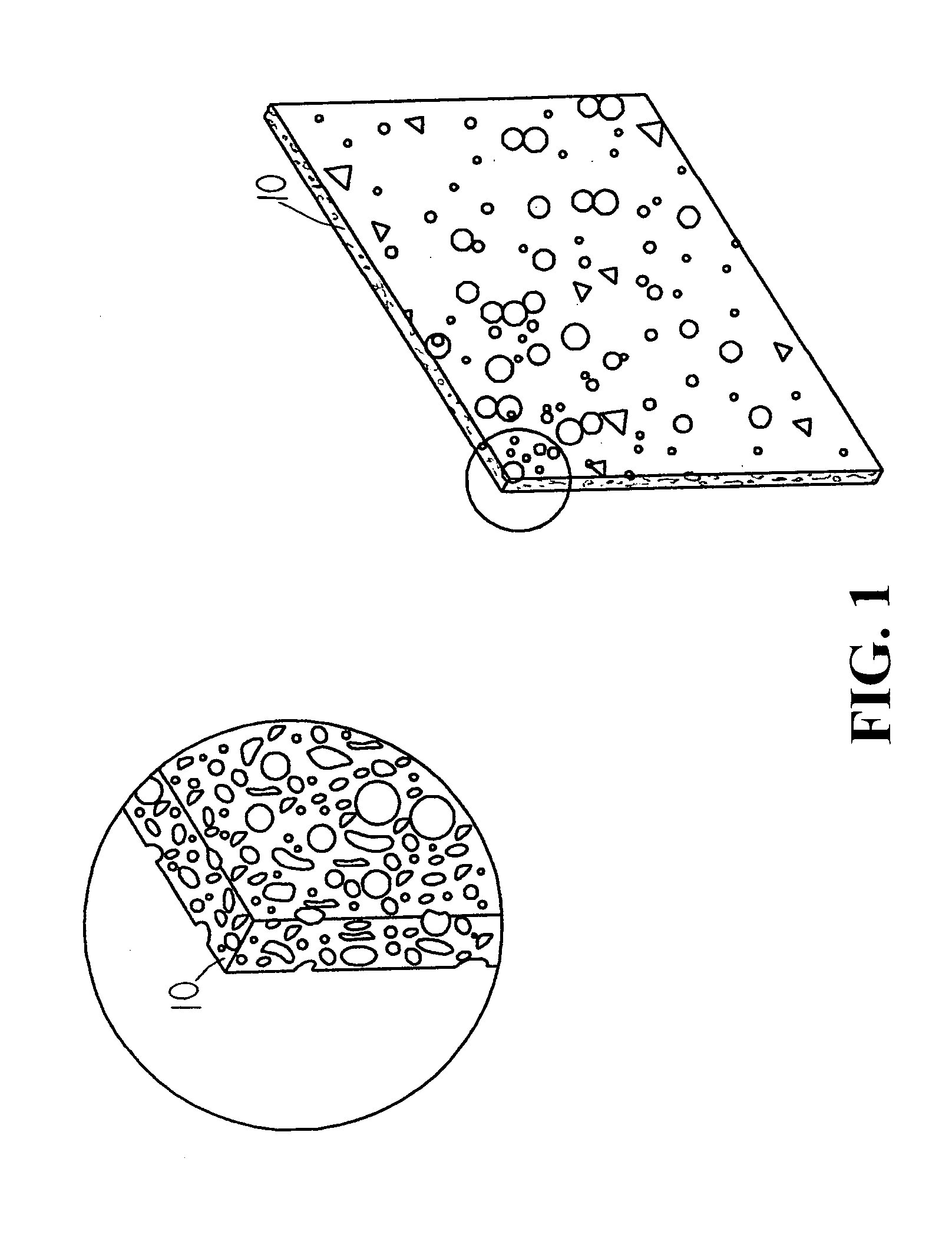
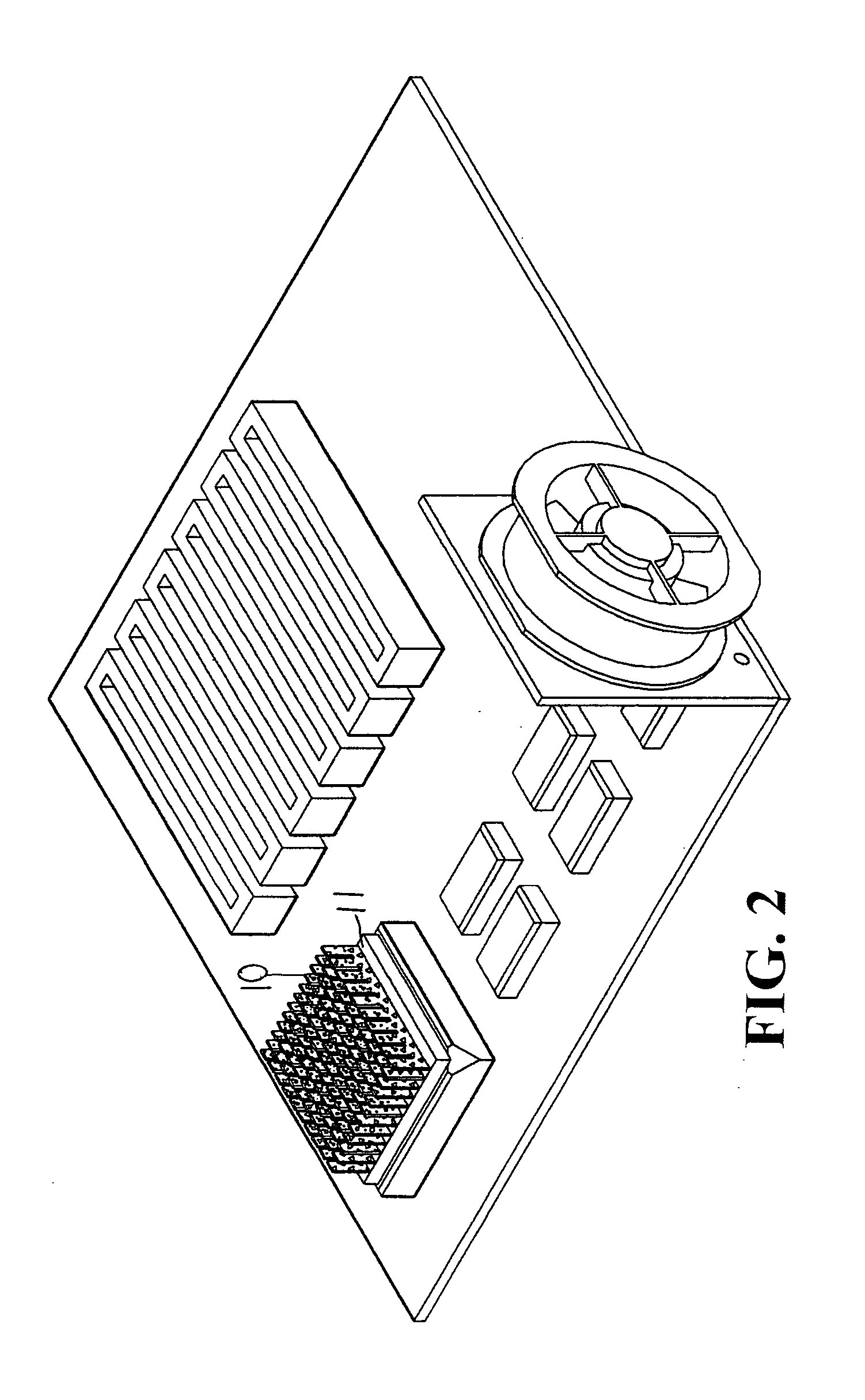
[0013] The following descriptions are of exemplary embodiments only, and are not intended to limit the scope, applicability or configuration of the invention in any way. Rather, the following description provides a convenient illustration for implementing exemplary embodiments of the invention. Various changes to the described embodiments may be made in the function and arrangement of the elements described without departing from the scope of the invention as set forth in the appended claims.

[0014] As shown in FIGS. 1 and 2, the fins 10 of a heat sink according to an embodiment of the present invention are made from metallic plates with high thermal conductivity. The metallic plates have multiple cavities or pores of irregular shapes and dimensions dispersed within the metallic plates. The porous metallic plates are appropriately cut in order to form pieces of thin and narrow fins 10. In an alternative embodiment, the porous metallic material could also be molded into the required ...


PUM


Abstract

A heatsink for electronic component is provided. The heatsink has its fins made from metallic plates having multiple cavities of irregular shapes and dimensions dispersed within the metallic plates. For fins made from these porous metallic plates, the cavities or pores significantly increase the surface areas of the fins exposed to the air and these fins, therefore, have a superior heat dissipation capability than those fins made of the same material but with no pores. When operated with an auxiliary fan, the pores of the fins provide additional passages to the air flow and the fins are able to achieve a better wind-chill effect.

Description

BACKGROUND OF THE INVENTION [0001] (a) Technical Field of the Invention [0002] The present invention generally relates to heatsinks, and more particularly to heatsinks whose fins are made from metallic plates having a plurality of pores. [0003] (b) Description of the Prior Art [0004] As shown in FIG. 3, a conventional heatsink usually contains multiple thin narrow plates 20 called fins, and the fins 20 are densely arranged in an array on the heatsink. The heatsink and its fins 20 are usually made of metallic materials having a high thermal conductivity. The heatsink is usually installed on top of an electronic component (e.g., an integrated circuit chip) and the heat produced by the electronic component is conducted to the fins 20 of the heatsink and dissipated to the air. As such, the electronic component and other near-by components will not become damaged or malfunctioned from the high temperature caused by the accumulation of heat. [0005] It should be obvious that the reason why...

Claims


Application Information

Patent Timeline
Patent Type & Authority Applications(United States)
IPC IPC(8): H05K7/20
CPCH01L23/3733H01L2924/0002H01L2924/00
Inventor KUO, CHING-LIN
Owner KUO CHING LIN
Why Eureka
Try Eureka