Heat sink and information processing device

a technology of information processing device and heat sink, which is applied in the direction of cooling/ventilation/heating modification, semiconductor devices, basic electric elements, etc., can solve the problems of time and effort required to remove the heat sink from the lsi package, deterioration of the heat absorption capability of the heat sink, etc., to suppress the deterioration of the heat absorption capability and reduce the time and labor.

Inactive Publication Date: 2007-03-01
FUJITSU LTD
View PDF4 Cites 1 Cited by
  • Summary
  • Abstract
  • Description
  • Claims
  • Application Information

AI Technical Summary

Benefits of technology

[0024] According to the present invention, there can be provided the heat sink that can reduce time and labor for removing the heat sink from the heating element while suppressing deterioration of heat absorption capability and an information processing device including the heat sink.

Problems solved by technology

However, time and effort may be required to remove the heat sink from the LSI package because the greases and the like are solidified, and the like.
However, the proposal is disadvantageous in that the heat absorption capability of the heat sink is deteriorated due to the recessed section formed on the bottom surface acting as a contact surface.

Method used


Image

  • Heat sink and information processing device
  • Heat sink and information processing device
  • Heat sink and information processing device

Examples


first embodiment

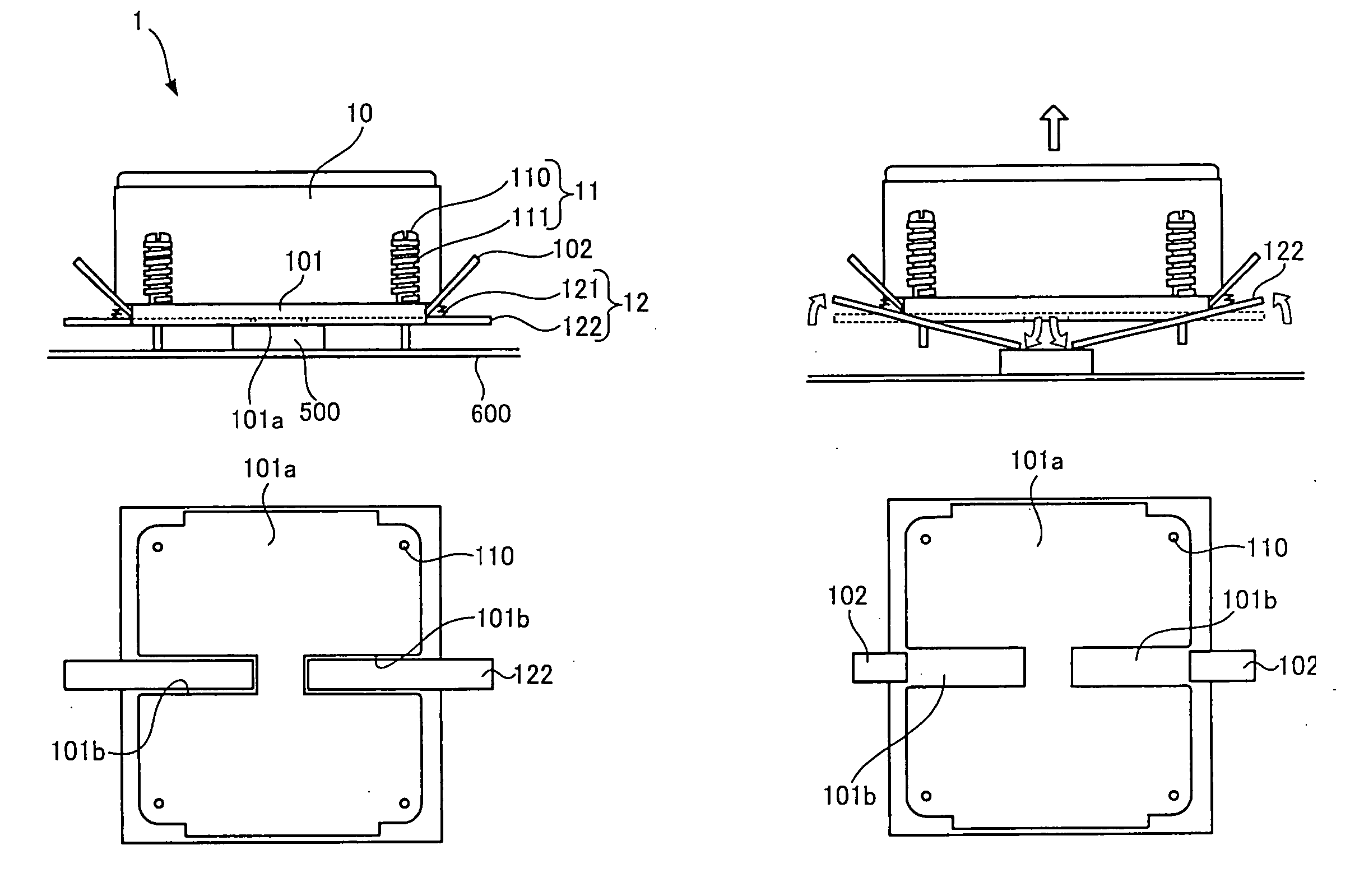
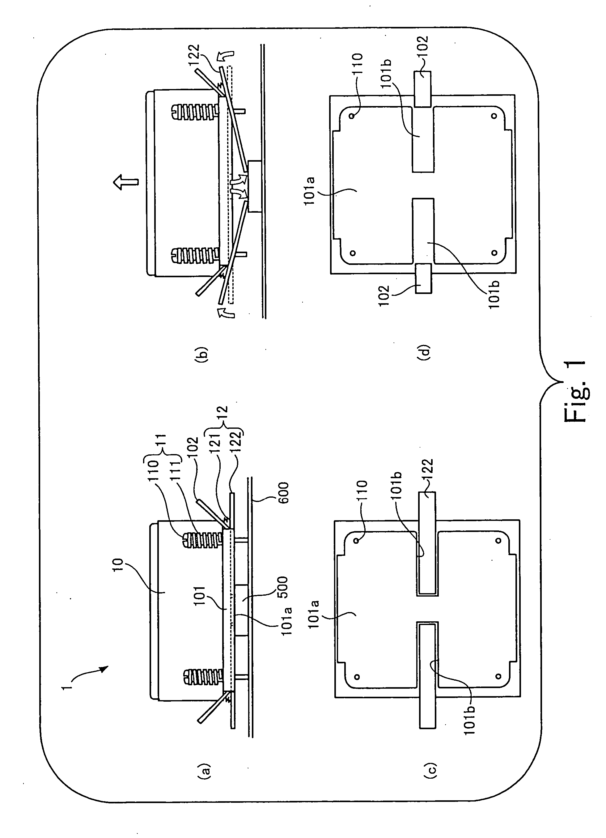
[0031]FIG. 1 is a view of a first embodiment common to a first heat sink of the present invention and a first information processing device of the present invention.

[0032] Part (a) of FIG. 1 shows a heat sink 1 disposed on an LSI package 500, and Part (b) of FIG. 1 shows the heat sink 1 which is being removed from the LSI package 500.

[0033] The heat sink shown in Part (a) of FIG. 1 is a heat absorption member composed of a main body 10, fixing sections 11, and manipulating sections 12 and disposed on an LSI package 500, which is attached to an electric substrate 600, through grease to absorb the heat of the LSI package 500.

[0034] A plate 101 is attached to the bottom surface of the main body 10 of the heat sink 1 shown in Part (a) of FIG. 1, and the plate 101 is in contact with the LSI package 500 through the bottom surface 101a thereof. Note that bottom surface 101a of the plate 101 corresponds to an example of the contact surface of the present invention.

[0035] Each of the mani...

second embodiment

[0042] Next, a second embodiment common to the first heat sink of the present invention and the first information processing device of the present invention will be explained.

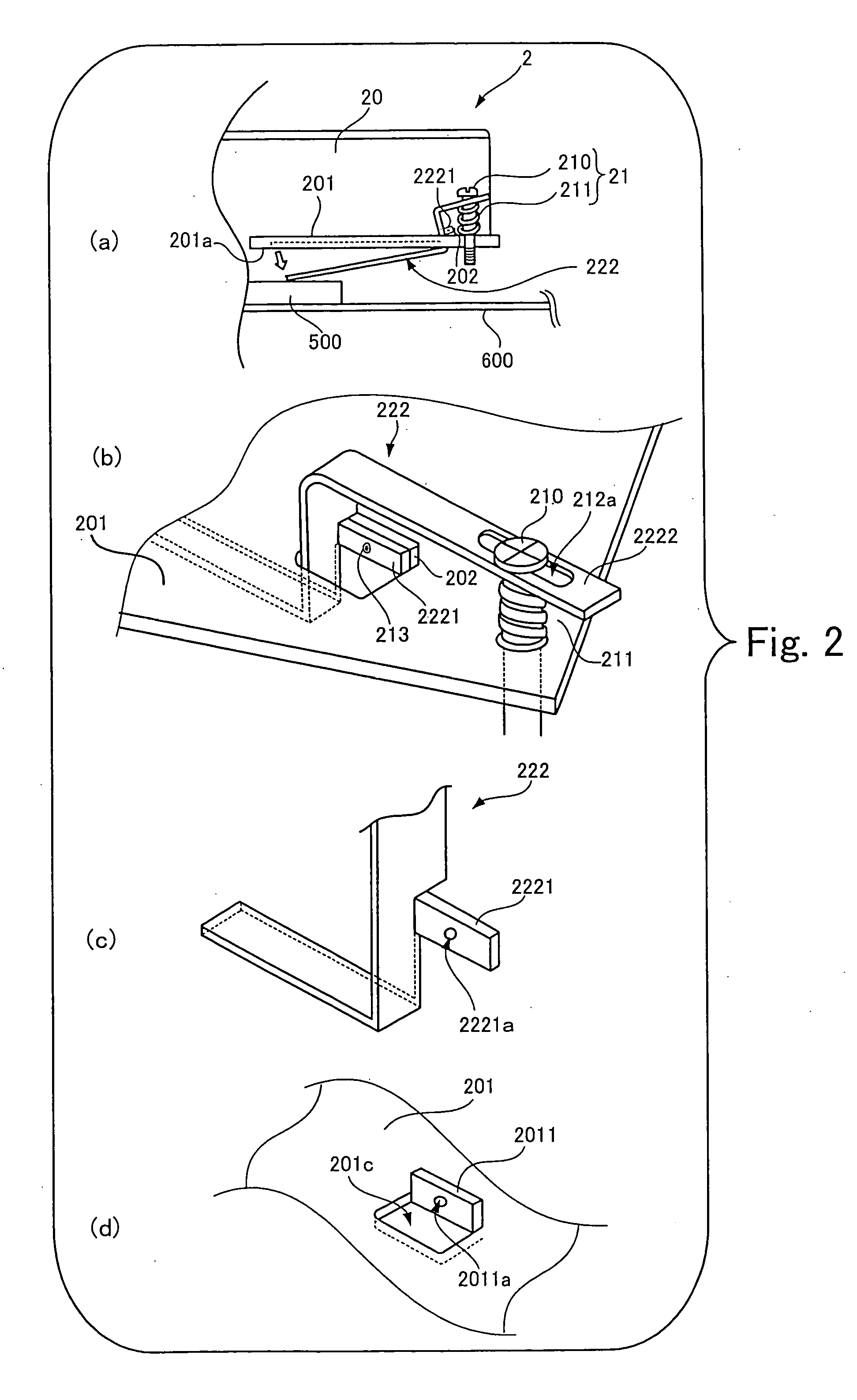
[0043]FIG. 2 is a view showing a heat sink of the second embodiment.

[0044] The heat sink 2 shown in FIG. 2 is different from the heat sink 1 shown in FIG. 1 in that insertion members 222 of the heat sink 2 are disposed together with fixing sections 21, in contrast that, in the heat sink 1 shown in FIG. 1, the fixing sections 11 composed of the screws 110 and the springs 111 and the insertion members 122 are disposed at different positions. Note that the members shown in FIG. 2, which are of the same type as the members shown in FIG. 1, are denoted by the same reference numerals as those used in FIG. 1.

[0045] Part (a) of FIG. 2 is a view corresponding to Part (b) of FIG. 1 showing the heat sink 1 and shows that the insertion member 222 is turned in a direction where the bottom surface 201a of a main body 20 is...

third embodiment

[0052]FIG. 4 is a schematic configurational view of the heat sink of a

[0053] Part (a) of FIG. 4 shows that a heat sink 3 of the third embodiment is disposed on an LSI package 500, an insertion member 322 is inserted into a recessed groove 301b formed to the bottom surface 301a of a plate 301 fixed to the bottom surface of a main body 30, and screws 110 are screwed thereinto and tightened.

[0054] Part (b) of FIG. 4 shows the insertion member 322 extracted by removing the screws 110 tightened in Part (a) of FIG. 4.

[0055] Part (c) of FIG. 4 shows a case in which the heat sink 3 shown in Part (a) of FIG. 4 is observed from the bottom surface thereof.

[0056] In the heat sink 3 of the third embodiment, the adhesion of the plate 301 with the LSI package 500 due to solidified grease and the like can be partly broken by extracting the insertion member 322 when the heat sink 3 is removed from the LSI package 500. Further, since the thickness of the insertion members 322 permits them to fill ...


PUM


Abstract

A heat sink that is disposed on a heating element and absorbs the heat generated by the heating element includes: a contact surface to which recessed grooves are formed and the region of which excluding the recessed grooves is in contact with the heating element; insertion members having a thickness, which permits them to fill the recessed grooves, and come into contact with the heating element by being inserted into the recessed grooves; and a turning mechanism that separates the contact surface from the heating element by turning the insertion members in response to a manipulation while abutting the extreme ends of the insertion members against the heating element. With such arrangement, there can be provided the heat sink that can reduce time and effort for removing the heat sink from the heating element while suppressing deterioration of heat absorption capability and an information processing device including the heat sink.

Description

BACKGROUND OF THE INVENTION [0001] 1. Field of the Invention [0002] The present invention relates to a heat sink disposed on a heating element and absorbing the heat generated by the heating element and to an information processing device including the heat sink. [0003] 2. Description of the Related Art [0004] Heretofore, a heat absorption member, which is called a heat sink, is disposed on an LSI package, which is attached to an electric substrate, through grease and the like for improving thermal conductivity to absorb the heat generated by the LSI package. [0005] The LSI package attached to the electric substrate may be replaced in its entirety, and, in this case, the heat sink is removed once from the LSI package. [0006] However, time and effort may be required to remove the heat sink from the LSI package because the greases and the like are solidified, and the like. [0007] To cope with this problem, there is a proposal for simply removing a heat sink from an LSI package (refer ...

Claims


Application Information

Patent Timeline
Patent Type & Authority Applications(United States)
IPC IPC(8): H05B1/02
CPCH01L23/4093H01L2924/0002H01L2924/00
Inventor NISHIKAWA, ERIKO
Owner FUJITSU LTD
Why Eureka
Try Eureka