

Radio transmission apparatus and peak power suppression method in multicarrier communication
a transmission apparatus and multi-carrier technology, applied in multiplex communication, orthogonal multiplex, frequency-division multiplex, etc., can solve the problems of signal distortion, communication characteristics (, ber: bit error rate) deterioration, etc., to prevent deterioration in throughput and transmission efficiency degradation, the effect of reducing the peak power
- Summary
- Abstract
- Description
- Claims
- Application Information
AI Technical Summary
Benefits of technology
Problems solved by technology
Method used
Image

Examples
embodiment 1
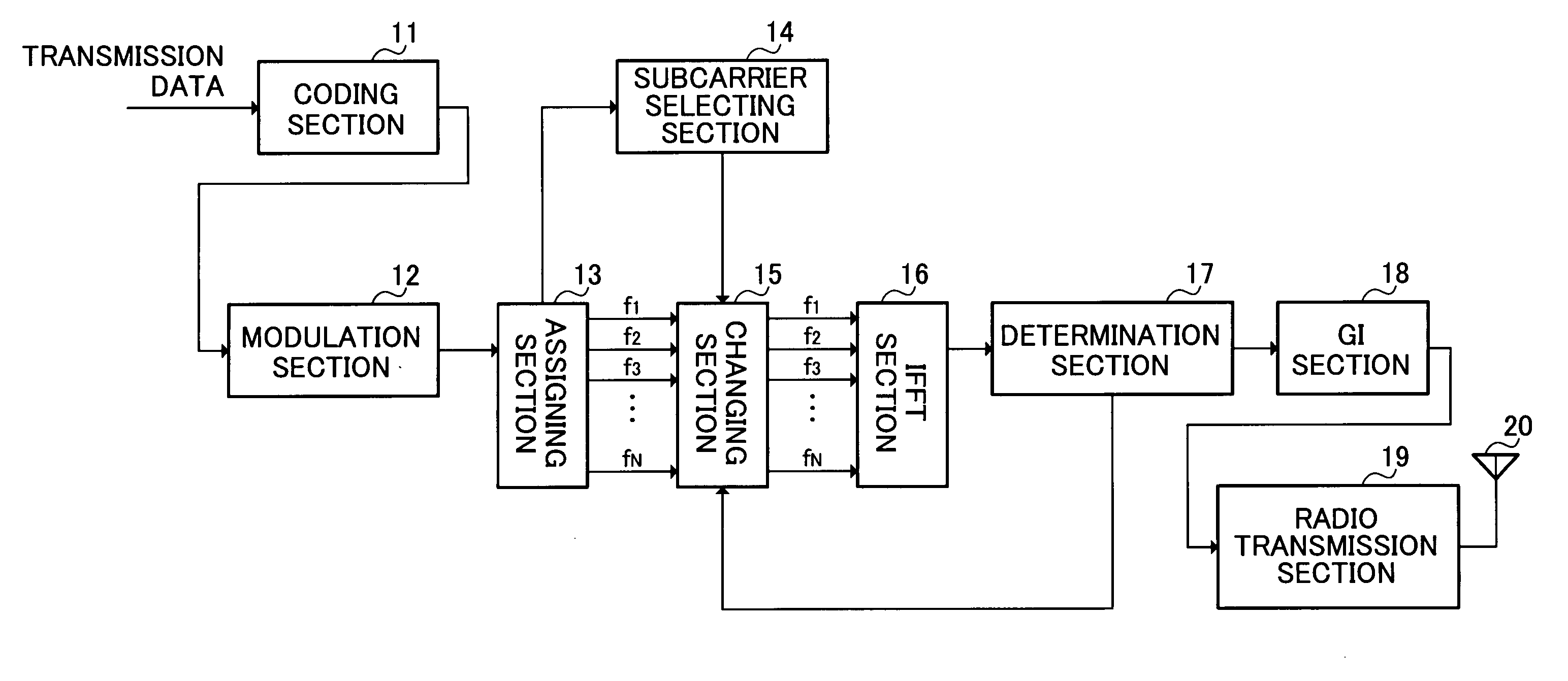
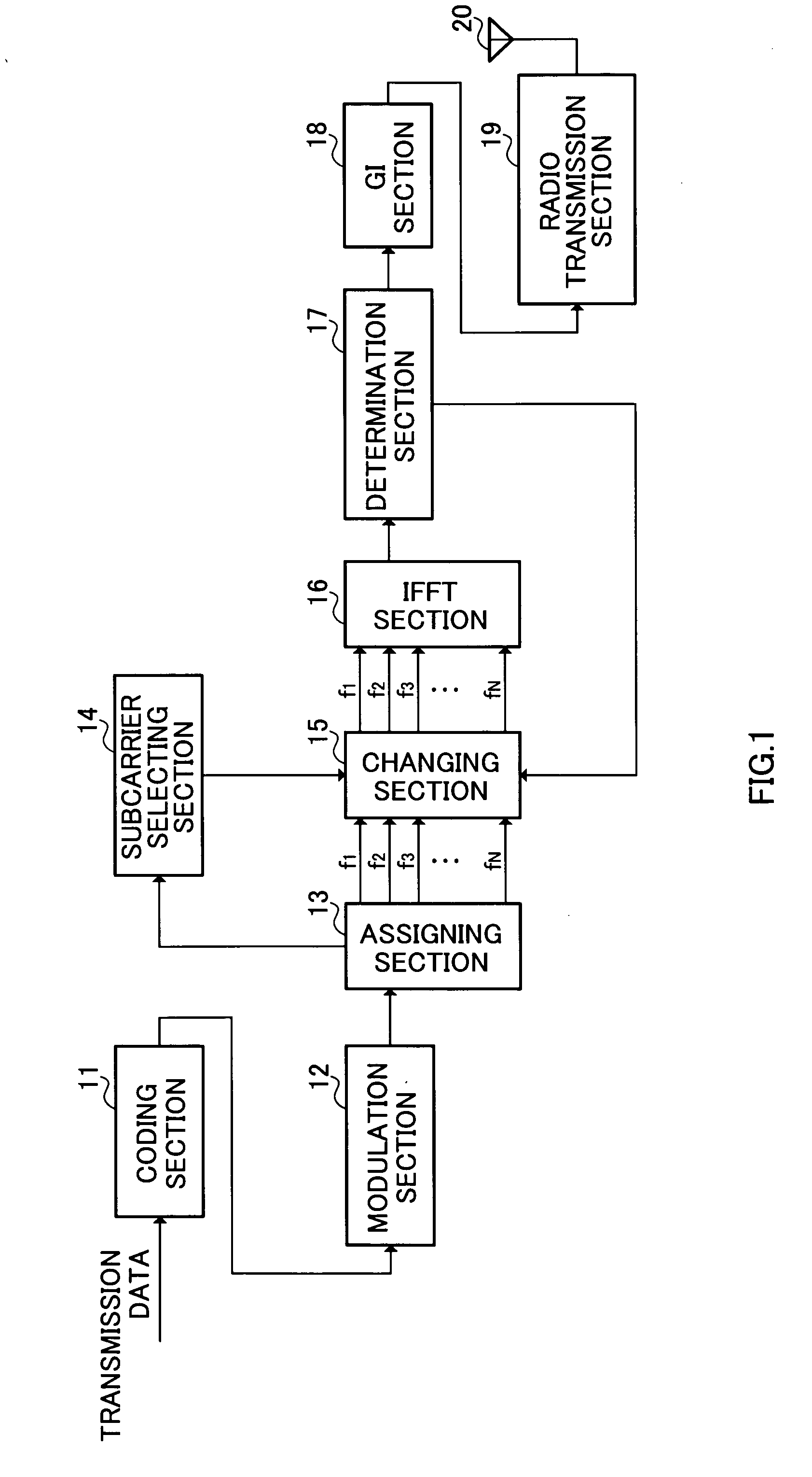
[0038]FIG. 1 is a block diagram illustrating the configuration of the radio transmission apparatus according Embodiment 1 of the present invention. The radio transmission apparatus shown in FIG. 1 has coding section 11, modulation section 12, assigning section 13, subcarrier selecting section 14, changing section 15, inverse fast Fourier transform (IFFT) section 16, determination section 17, guard interval (GI) section 18, radio transmission section 19, and antenna 20.
[0039] Coding section 11 performs error correcting coding on transmission data (bit sequence).
[0040] Modulation section 12 generates a symbol from the coded data, places the generated symbol at one of a plurality of signal points on the IQ plane, and thereby modulates the data. The plurality of signal points on the IQ plane are defined according to the modulation scheme used in modulation section 12, and this will be described later in detail.
[0041] Assigning section 13 transforms the modulated symbol input in serie...
example 1
[0057] In Example 1, the phase and amplitude of a subcarrier is changed in the change range shown in FIG. 7. More specifically, changing section 15 multiplies the subcarrier selected in subcarrier selecting section 14 by ak as shown in following Equation (1):
akp·ejθ (1)
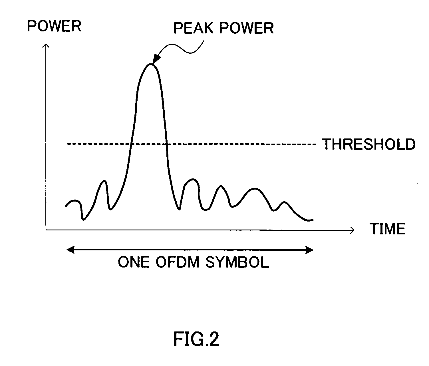
[0058] where p is a variable for changing the amplitude and is defined as 0<p<1, θ is a variable for changing the phase and is defined as −π / 4<θ<π / 4, and these are both random variables that change per subcarrier. k is 1, 2, . . . , N (N is the total number of subcarriers contained in one OFDM symbol). By thus changing θ randomly and changing the phase of each of subcarriers, it is possible to make the subcarriers out of phase, and, as a result, it is possible to suppress peak power of the OFDM symbol. Further, since p is defined as 0<p<1, the change range lies inside the amplitude increase / decrease boundary (part of a circle with a radius of 1) , and a subcarriers after the change always has lower amplitude and po...
example 2
[0059] In Example 2, the phase and amplitude of a subcarrier is changed in the change range (within the range of a circle with the original signal point as the center) shown in FIG. 8. More specifically, changing section 15 adds ak shown in above-mentioned Equation (1) to the subcarrier selected in subcarrier selecting section 14. However, in Example 2, where p is defined as 0<p<1 / √2, θ is defined as 0<θ≦2π, and these are both random variables that change per subcarrier. In Example 2, since the change range has a larger area outside the amplitude increase / decrease boundary than inside the amplitude increase / decrease boundary, the transmission power of the OFDM symbol increases with probability. By thus increasing the transmission power of an OFDM symbol, the error rate in the radio reception apparatus can be decreased, as compared with Example 1.
PUM
 Abstract
Description
Claims
Application Information