
Suture reinforcement material for automatic suturing device

a technology of suture reinforcement and suture, which is applied in the field of suture reinforcement material, can solve the problems of air leakage from the sutured area, tissue damage or tear may arise, and the sewing method requires a lot of time and skill, and achieves the effect of smooth removal

Active Publication Date: 2007-03-01
GUNZE LTD
View PDF20 Cites 354 Cited by
  • Summary
  • Abstract
  • Description
  • Claims
  • Application Information

AI Technical Summary

Benefits of technology

The invention provides a novel suture reinforcement material for an automatic suturing device that can be easily manufactured without advanced skill and from which a thread can be smoothly removed regardless of the material used and the sewing pitch of the suture reinforcement material. The suture reinforcement material has various characteristic structures, such as a tubular shape, tapering or bag-like shape, and includes at least one portion made of a biodegradable and bioabsorbable material. The material can be fitted to an automatic suturing device cartridge or frame. The technical effects of the invention include improved suturing efficiency and accuracy, as well as reduced risk of thread unraveling and untightening.

Problems solved by technology

However, when such a suturing device is applied to pulmonary surgery, etc., air leakage may occur from the sutured area.
In addition, when applied to soft tissues, problems of tissue damage or tear may arise.
However, the tubular suture reinforcement material manufactured using temporary adhesion is disadvantageous in that sheet-like materials joined by adhesion tend to separate from each other, and the tubular suture reinforcement material manufactured using a running stitch is disadvantageous in that the sewing manner requires a lot of time and skill, and removal of thread is difficult depending on the kind of sheet-like material, sewing pitch, etc.

Method used


Image

  • Suture reinforcement material for automatic suturing device
  • Suture reinforcement material for automatic suturing device
  • Suture reinforcement material for automatic suturing device

Examples


embodiment 1

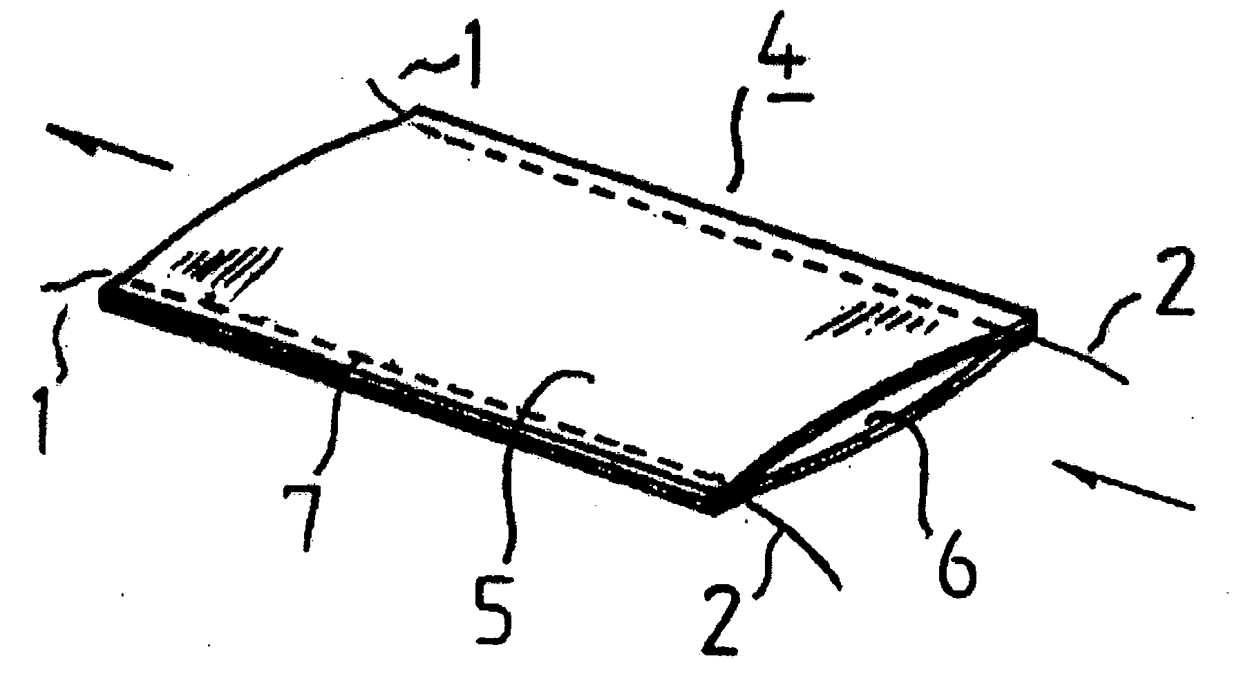
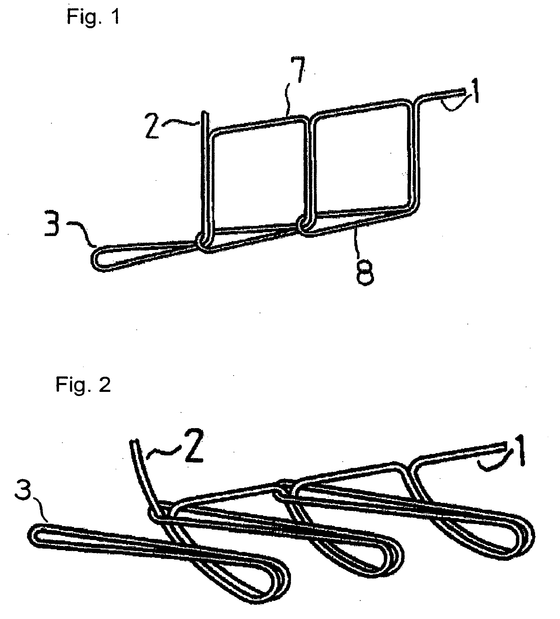
[0065]FIGS. 8 and 9 show the suture reinforcement material of the invention manufactured by the stitching style shown in FIG. 1. FIG. 8 is a tubular suture reinforcement material 4 that is prepared by stacking a biodegradable and bioabsorbable nonwoven fabric 5 and a stretchable powernet 6, and sewing together both ends of the stacked materials with a DH-type chain stitching machine manufactured by Pegasus. FIG. 9 shows a bag-like tubular suture reinforcement material 4 whose tip part is closed. The bag-like tubular suture reinforcement material is obtained by folding one sheet of the nonwoven fabric 5, stacking both ends, and sewing them in a tubular shape with the same sewing machine as described above.

[0066] Although not illustrated, as a modified example of FIG. 8, a suture reinforcement material whose tip part is sewed in a tapering manner can also be mentioned.

[0067] In either case, the thread end(s) 2 at the sewing end(s) are suitably extended for easy removal of thread.

[0...

embodiment 2

[0069]FIG. 12 shows a structure of a suture reinforcement material according to another embodiment. The suture reinforcement material is a tubular suture reinforcement material, which is obtained by stacking a biodegradable and bioabsorbable nonwoven fabric 5 and a stretchable powernet fabric 6, and sewing both ends. The thread end 1 at the sewing start is joined to the powernet fabric 6 and the thread ends 2 at the both sewing ends are tied to form a ring (annular).

[0070] This structure with the ring-shaped thread end 2 at the sewing end facilitates the handling of the material and the removal of the thread. Further, since the thread end 1 at the sewing start is tied to the powernet material 6, the power net material is easily removed with the thread after a surgical operation.

embodiment 3

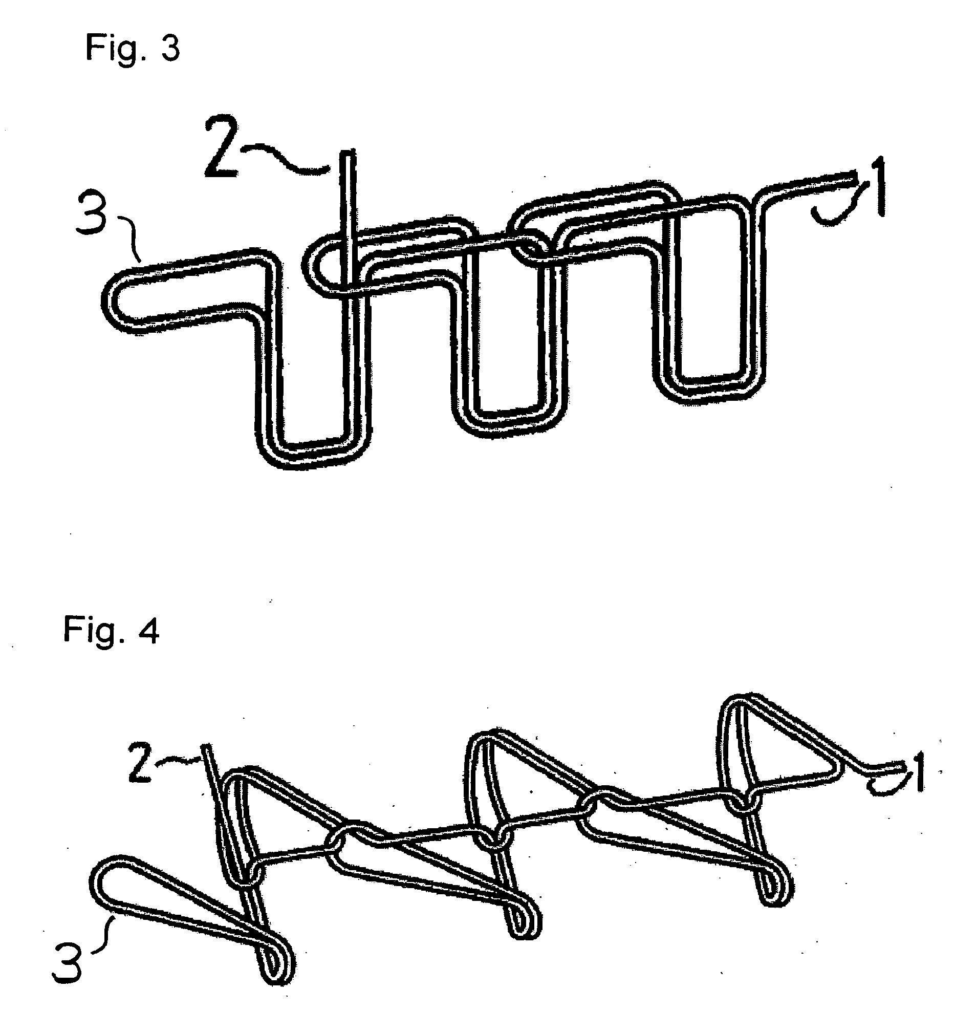
[0071]FIGS. 13 and 14 each show another suture reinforcement material according to another embodiment that is structured to prevent the thread ends 2 at the sewing ends from unraveling.

[0072]FIG. 13 shows that a stopper 9 passes through loops 3 of the thread ends 2 at the sewing end. The stopper 9 may be thread, finely-cut material or film, etc., and materials other than a fiber may be used. A suitably rigid material that can easily be passed through the loop and drawn out from the loop is preferable.

[0073]FIG. 14 shows a suture reinforcement material in which the thread ends 2 at the sewing ends are passed through the anterior loops 3 continuous to the thread ends 2, thereby preventing the thread ends 2 at the sewing ends from unraveling as described above. The thread end 2 is passed through the loop 3 by the following steps 1 to 4 as shown in the figure. The thread ends 2 at the sewing ends are passed through the loop 3, and finally, the thread ends 2 are pulled to secure it.

[0...


PUM


Abstract

The present invention relates to a tubular suture reinforcement material suitable for use in automatic suturing devices that are widely used in surgical operations, etc. More specifically, the present invention relates to a tubular suture reinforcement material with which a tubular shape is easily obtained to thereby increase its productivity, and removal of thread is easily achieved. The present invention aims to overcome drawbacks such that sheet-like materials joined by the conventional temporary adhesion easily separate from each other, and the tubular suture reinforcement material manufactured using a running stitch requires a lot of time and skill, and removal of the thread is difficult depending on the kind of sheet-like material, sewing pitch, etc. More specifically, the present invention relates to a tubular suture reinforcement material for an automatic suturing device, wherein both ends of one or two sheet-like materials are sewed using a chain stitch (intralooping stitch) with a single thread to form a tubular shape, and one or two thread ends at one or two sewing ends are suitably extended.

Description

RELATED APPLICATIONS [0001] This application is the U.S. National Phase under 35 U.S.C. 371 of International Application No. PCT / JP2004 / 010566, filed Jul. 16, 2004.TECHNICAL FIELD [0002] The present invention relates to a tubular suture reinforcement material suitable for use in automatic suturing devices that are widely used in surgical operations, etc. More specifically, the present invention relates to a tubular suture reinforcement material with which a tubular shape is easily obtained, productivity is high, and removal of thread is easily achieved. BACKGROUND OF THE INVENTION [0003] Hitherto, stapler-type automatic suturing devices containing a plurality of staples have been employed for suturing tissues. However, when such a suturing device is applied to pulmonary surgery, etc., air leakage may occur from the sutured area. In addition, when applied to soft tissues, problems of tissue damage or tear may arise. [0004] In order to solve the above problems, the applicant has alrea...

Claims


Application Information

Patent Timeline
Patent Type & Authority Applications(United States)
IPC IPC(8): A61B17/08A61B17/04A61B17/06A61B17/072
CPCA61B17/0483A61B2017/0477A61B17/07292A61B17/07207A61L17/00A61B17/04A61B17/06
Inventor SHIMOJI, HIROYUKIOHTANI, HITOSHI
Owner GUNZE LTD
Learn More