Method of manufacturing resin boot for constant-velocity universal joint

a manufacturing method and constant velocity technology, applied in the direction of manufacturing tools, surface layering apparatus, couplings, etc., can solve the problems of labor and time, inability to use a tripod boot while simultaneously a part of the tripod boot is grasped and pulled out, and inability to manufacture the tripod boot. , to achieve the effect of smooth removal from the core, superior manufacturing efficiency, and low cos

Inactive Publication Date: 2009-05-26
FUKOKU CO LTD
View PDF11 Cites 3 Cited by
  • Summary
  • Abstract
  • Description
  • Claims
  • Application Information

AI Technical Summary

Benefits of technology

[0014]An object of the present invention is to provide a manufacturing apparatus and a manufacturing method for a resin boot for a constant-velocity universal joint, and a resin boot for a constant-velocity universal joint, superior in manufacturing efficiency and inexpensive, in which the boot (tripod boot) for the constant-velocity universal joint, formed of the resin and integrated in secondary molding, can be smoothly removed from a core without being deformed.
[0022]According to the present invention, a plurality of ejection mechanisms (ejectors) are disposed in the positions avoiding the runner mechanism, the ejecting forces from the ejectors are applied onto the lower end surface of a tripod boot integrated by the secondary molding, and accordingly the tripod boot can be smoothly removed from the core with good efficiency.
[0023]Moreover, at least the abutment surface of the tip of the ejector is formed in such a shape (e.g., the circular shape, the broad shape) that the contact area with respect to the lower end surface of the other-end annular fastening portion increases. Accordingly, the uniform ejecting force can be exerted onto the lower end surface. As a result, the tripod boot integrated by the secondary molding can be efficiently removed from the mold without being deformed.

Problems solved by technology

Therefore, the method in which the air is blown out of the core to expand the tripod boot and simultaneously a part of the tripod boot is grasped and pulled out cannot be used.
In this case, the use of a method in which the tripod boot is pulled out of the core by a manual operation is also considered, but labor and time are required, and personnel expenses have also piled up.
As a result, a manufacturing efficiency of the tripod boot drops and a manufacturing cost rises.
However, in the manufacturing method of the tripod boot, a cooled state of the other-end annular fastening portion P3 of the tripod boot after (immediately after) the second molding is not complete (in a soft state in which the portion does not completely solidify (harden).
Therefore, when the other-end annular fastening portion P3 of the boot is extruded out of the core by the ejector, a portion on which an extruding force of the ejector acts is compressed in a vertical direction (extruding direction of the ejector) to expand in a lateral direction, the portion is pressure-welded to the core, and the tripod boot which is the second molded member is not easily removed (released) from the core in some case.

Method used


Image

  • Method of manufacturing resin boot for constant-velocity universal joint
  • Method of manufacturing resin boot for constant-velocity universal joint
  • Method of manufacturing resin boot for constant-velocity universal joint

Examples


Embodiment Construction

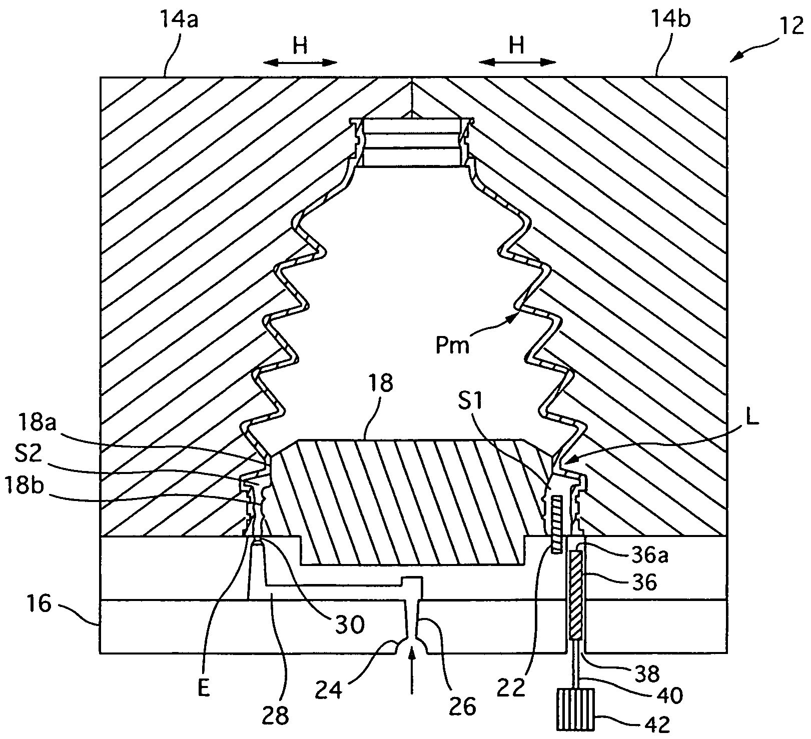
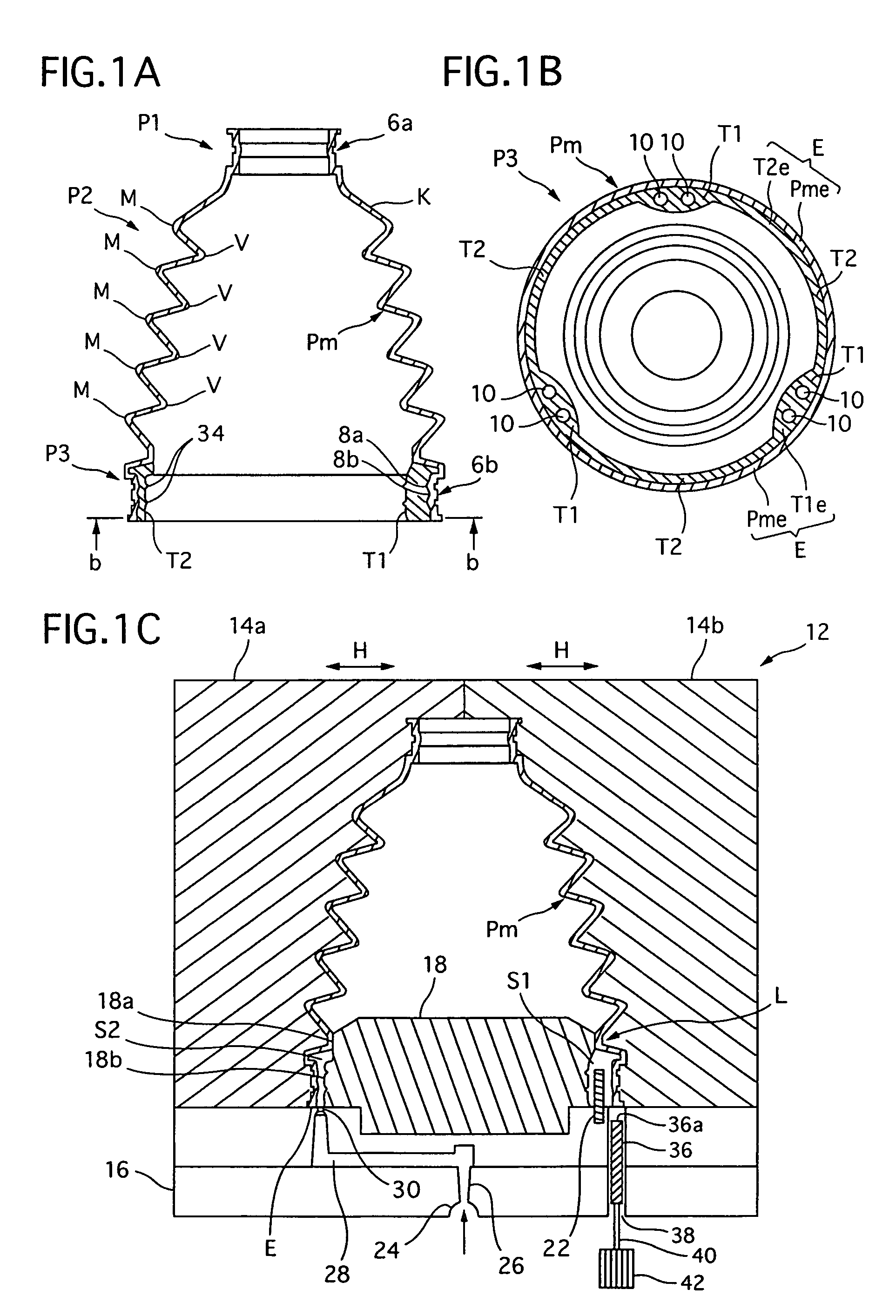
[0052]A manufacturing apparatus and method for a resin boot for a constant-velocity universal joint of the present invention will be described with reference to the accompanying drawings. It is to be noted that in the following description, a boot for a tripod joint (hereinafter referred to as the tripod boot) described above with reference to FIGS. 8A and 8B will be illustrated as an embodiment of the resin boot for the constant-velocity universal joint.

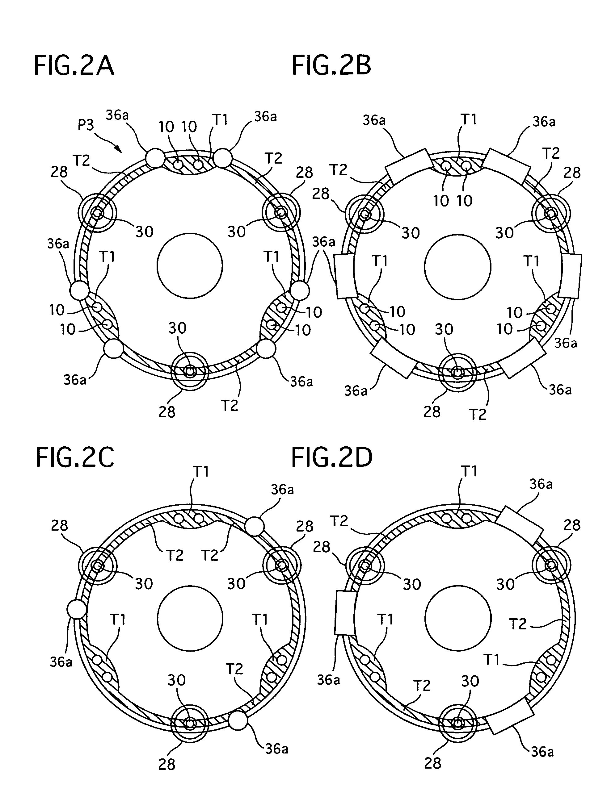
[0053]In the present embodiment, in the manufacturing apparatus and method of the tripod boot, an other-end annular fastening portion P3 of the tripod boot integrated by secondary molding can be smoothly removed (released) from a core 18 (see FIGS. 1C and 3A) without being deformed.

[0054]As shown in FIGS. 1A ad 1B, to constitute the tripod boot of the present embodiment, a boot main body Pm (see FIG. 8C) is integrally molded by a molten resin material (thermoplastic resin) in the existing primary molding step. Thereafter, in a secon...


PUM

PropertyMeasurementUnit
temperatureaaaaaaaaaa
thicknessesaaaaaaaaaa
thicknessaaaaaaaaaa

Abstract

There is disclosed a manufacturing apparatus and method which are capable of smoothly removing a tripod boot integrated by secondary molding from a core without deforming the boot and which are superior in manufacturing efficiency and which are inexpensive, and a resin boot for a constant-velocity universal joint. The apparatus includes: divided molds which hold a primarily molded resin boot main body from the outside; a core which holds the boot main body from the inside; a runner mechanism which injects / charges a molten resin material into a secondary molding space formed between the core and an other-end annular fastening portion; and an ejection mechanism for removing the tripod boot in which portions having different thicknesses are integrally and secondarily molded on an inner periphery of the other-end annular fastening portion from the core. The ejection mechanism is provided with a plurality of ejectors in positions avoiding gates of the runner mechanism, and ejecting forces are applied onto lower end surface of the other-end annular fastening portion of the tripod boot from the ejectors to stably and smoothly remove the tripod boot from the core.

Description

BACKGROUND OF THE INVENTION[0001]The present invention relates to a manufacturing apparatus and a manufacturing method for a resin boot for a constant-velocity universal joint, and a resin boot for a constant-velocity universal joint, which protects the constant-velocity universal joint for use, for example, in driving shafts or propeller shafts of cars.PRIOR ART[0002]Various types of boots for constant-velocity universal joints (e.g., boots for constant-velocity universal joints on an inboard side (engine side) and on an outboard side (tire side)) are attached to the constant-velocity universal joints for use, for example, in driving shafts or propeller shafts of cars in order to seal grease which is a lubricant and to prevent invasion of dust, water and the like from the outside.[0003]For example, as shown in FIGS. 8A and 8B, in a boot for a constant-velocity universal joint, a one-end annular fastening portion P1 which can be fastened to a shaft portion 2a of a constant-velocity ...

Claims


Application Information

Patent Timeline
Patent Type & Authority Patents(United States)
IPC IPC(8): B29C45/14B29C49/70B29C45/26B29C45/40B29C45/44B29C49/56B29L31/30
CPCB29C45/14336B29C45/40B29C45/14598B29C45/2628B29C45/44B29C2045/1445B29C2045/4063B29C2045/4492B29C2049/2069B29L2031/703F16D3/845F16D3/2055B29C49/70B29C49/56
Inventor SUEOKA, KAZUHIKOTAKADA, YASUJI
Owner FUKOKU CO LTD
Why Eureka
Try Eureka