Cathode plate

Inactive Publication Date: 2007-03-08
XSTRATA QUEENSLAND
View PDF1 Cites 6 Cited by
  • Summary
  • Abstract
  • Description
  • Claims
  • Application Information

AI Technical Summary

Benefits of technology

[0016] The above arrangement aims to ameliorate some of the aforementioned disadvantages. In particular, by cropping or cutting the normal right angle corners from the cathode blade, there is no need for a bottom plug in the edge strip. Silicone or other similar filler material may be used to fill the bottom of the edge strip and thereby inhibit copper growth in that area.
[0017] In a preferred embodiment, the bottom edge and / or corner edge portions include a groove such as a V-groove to assist in separation of the copper into two separate sheets, from the cathode blade.

Problems solved by technology

Any such movement or damage of the edge strip can be extremely detrimental to the process.
In particular, it is both costly and time consuming to replace or reposition the edge strip protectors.
Another disadvantage arises from the deposition of metal on that portion of the cathode plate held within the edge strip.
In some instances, the ingress of electrolyte is sufficient to cause metal to be deposited on that portion of the cathode blade held within the edge strip thereby deforming and potentially detaching the edge strip from the cathode blade.
However, a perennial problem remains, which is the growth of the deposited metal on the exposed lower end portion of the cathode blade, at either end of the bottom edge.
Generally, this does not cause structural failure of the edge strip, however, once the metal is stripped from the cathode blade, these additional deposits or ‘dags’ can remain on the stripped metal providing an unattractive product.
In severe cases, these deposits act to bridge the metal sheets stripped from either side of the cathode blade, making their separation more difficult.

Method used


Image

  • Cathode plate
  • Cathode plate
  • Cathode plate

Examples


Embodiment Construction

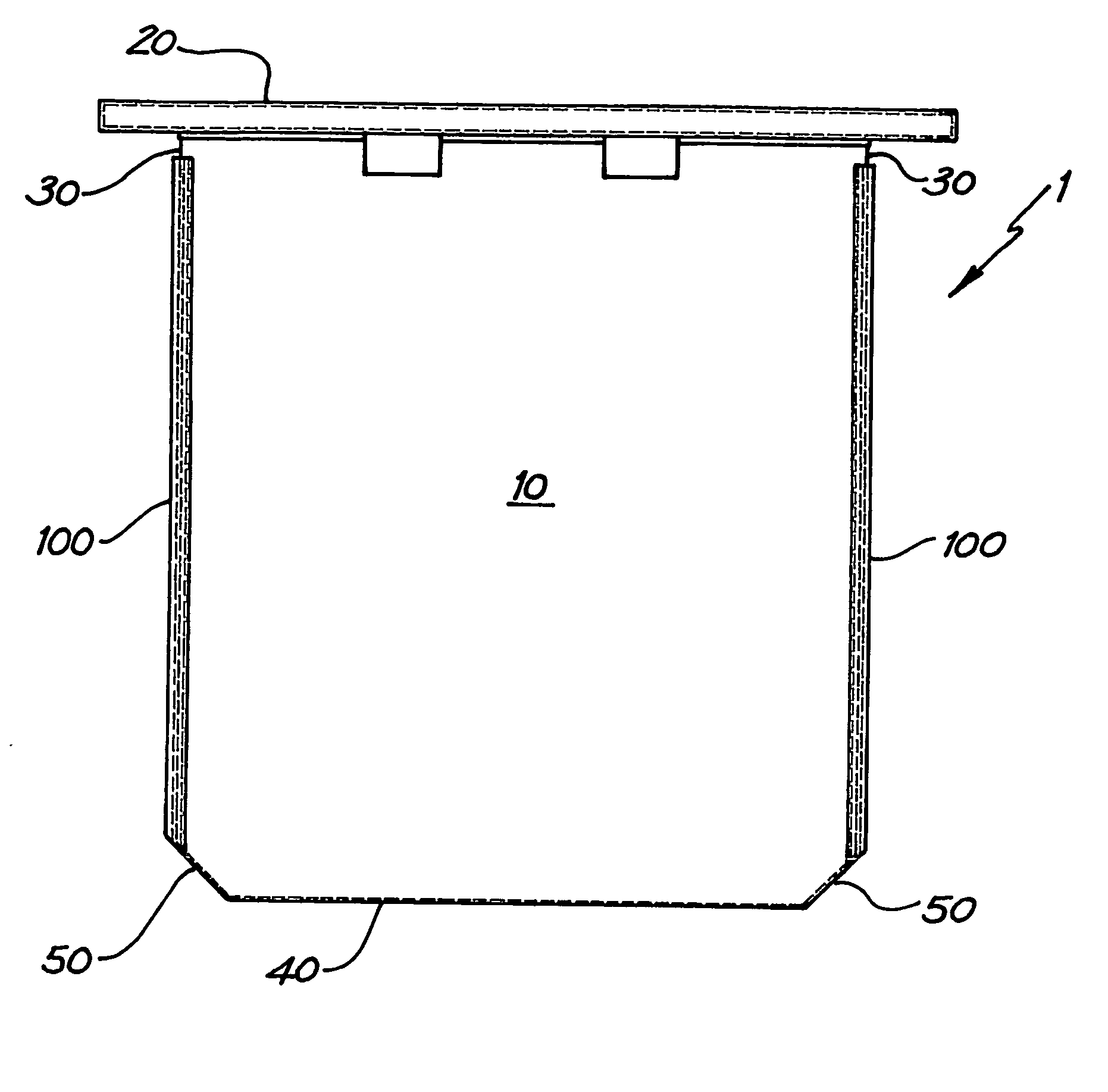
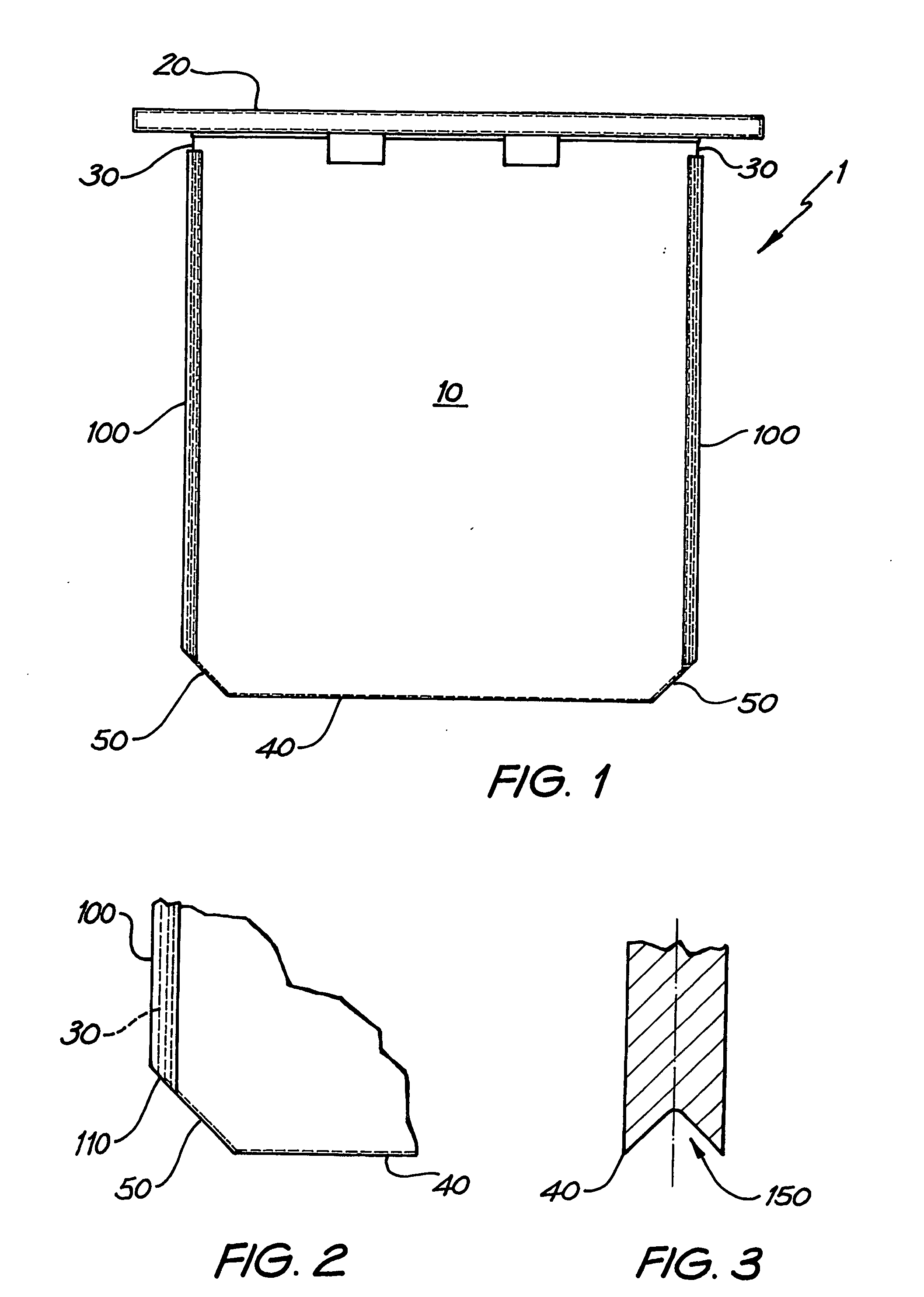
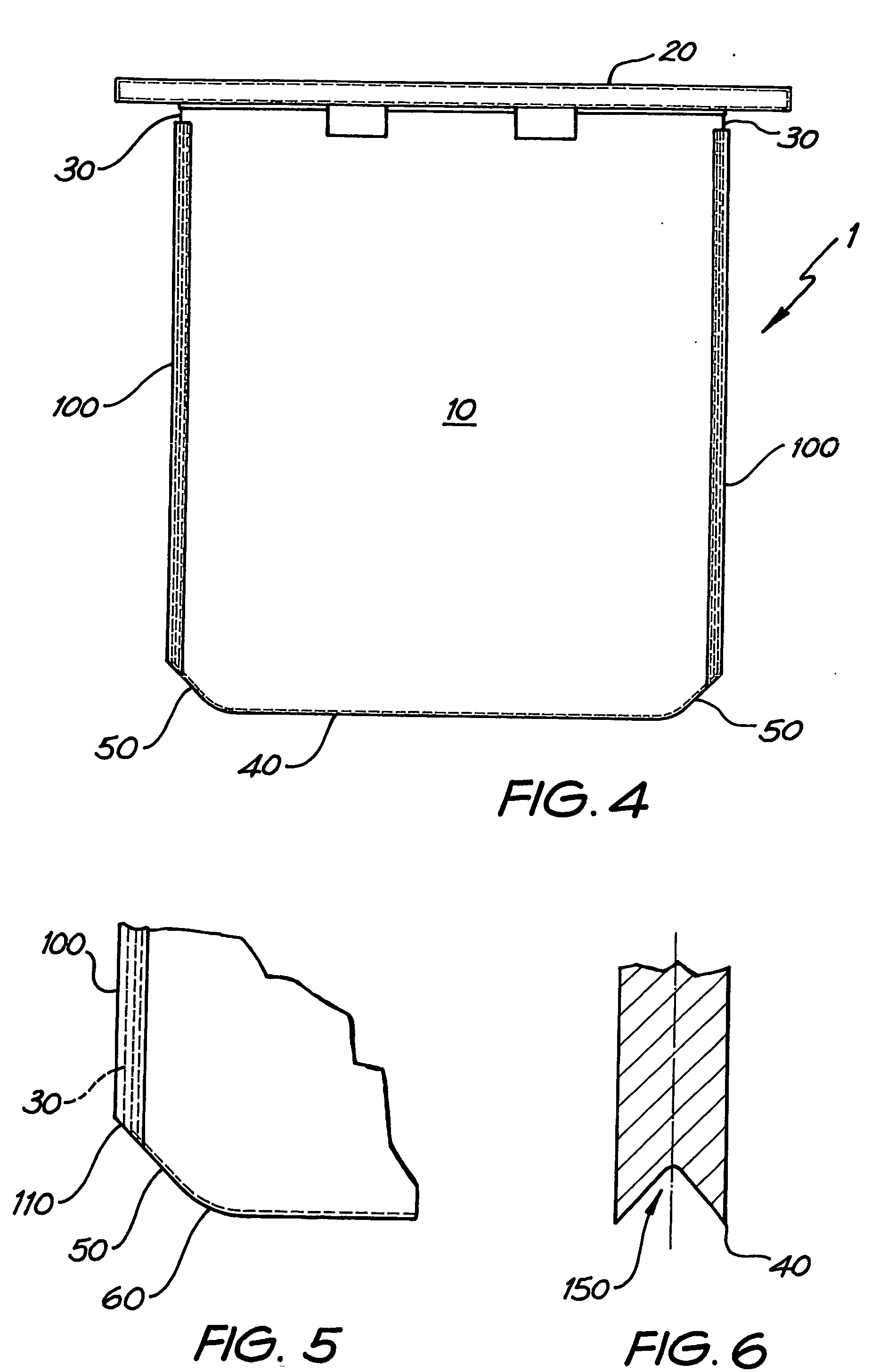
[0026] Referring firstly to FIGS. 1 and 2, the cathode plate 1 comprises a cathode blade 10 and hanger bar 20 connected along the top edge of the blade 10. As is well known in the art, the hanger bar 20 supports the blade 10 within an electrolytic bath and provides electric current to the blade for deposition of metal.

[0027] On the other three sides, the area of the blade is defined by side edges 30 and horizontal bottom edge 40. The periphery of the blade 10 is defined by hanger bar 20 at the upper periphery, side edges 30, at the side peripheries and bottom edge 40 at the lower periphery. The side edges extend downwardly from hanger bar 20 but terminate short of the lower periphery. Bottom edge 40 similarly terminates short of the side periphery defined by side edges 30. Either end of the horizontal edge 40 is joined to its respective side edge 30 by means of corner edge portion 50. In the embodiment shown, corner edge portion 50 is a straight edge between bottom edge 40 and side...


PUM

PropertyMeasurementUnit
Angleaaaaaaaaaa
Areaaaaaaaaaaa

Abstract

A cathode plate (1) comprises a cathode blade (10) and a hanger bar (20) attached to the upper end portion thereof to support the cathode blade (10) in an electrolytic bath. The area of the blade being defined by the hanger bar (20) at the upper periphery and two substantially parallel spaced apart side edges (30) extend from the hanger bar (20) and define the side periphery of the blade. A bottom end edge (40), which is substantially parallel to the hanger bar (20), defines the lower periphery of the blade. The side and bottom edges terminate short of the respective lower and side peripheries of the blade, with the corner edge portions (50) extending between and connecting opposite ends of the bottom edge (40) to the respective side edges (30).

Description

FIELD OF THE INVENTION [0001] The present invention relates to electrolytic recovery of metals, and in particular to cathode plates for use in electrolytic recovery of metals. BACKGROUND OF THE INVENTION [0002] Any discussion of the prior art throughout the specification should in no way be considered as an admission that such prior art is widely known or forms part of common general knowledge in the field. [0003] There are a number of processes for the electrolytic recovery or refining of metals. [0004] One particularly well known technique is the process for electro refining and / or electro winning of copper and other metals as developed by Mount Isa Mines Limited known as ISA PROCESS™ or ISA PROCESS 2000™ (Trade Marks of Mount Isa Mines Limited). In an electro refining process, unrefined anodes of a base metal such as copper are placed in an electrolytic bath and separated by cathode plates. Each cathode plate comprises a stainless steel blade held and supported in the bath by a h...

Claims


Application Information

Patent Timeline
IPC IPC(8): C25C7/02
CPCC25C7/02
Inventor WEBB, WAYNE KEITH
Owner XSTRATA QUEENSLAND
Why Eureka
Try Eureka